Amorphous carbon films have been widely recognized for their exceptional tribological properties, including low friction coefficients and extended wear life, making them suitable for protective coatings in various applications. Numerous studies have explored the friction and wear mechanisms of these films, revealing that their intrinsic chemical, structural, and mechanical properties, as well as external interactions with their environment, significantly influence their behavior [1-4]. Recently, nanostructured carbon films (NCFs) with graphene-like nanocrystallites have gained significant attention, offering excellent tribological performance and high electrical conductivity. These materials hold great potential as novel coatings in the field of nanotribology.
Several researchers have focused on growing carbon films with graphite-like nanocrystallites. For example, [5] synthesized a nanocrystallite carbon film with an sp2 network structure using laser-arc evaporation, achieving high hardness and elastic recovery. Employed electron cyclotron resonance (ECR) sputtering to prepare a carbon nanocrystallite film, investigating its electrical conductivity and hardness. Developed tetrahedral amorphous carbon (ta-C) films using the filtered cathodic vacuum arc (FCVA) method, examining thermally induced sp2 clustering in ta-C films. [6] deposited ta-C films with varying carbon ion impact energies, observing a structural transformation from amorphous to sp2-rich, containing graphite layers. Our previous research on electron or ion irradiation of carbon films demonstrated the facilitation of nanostructure formation, enabling precise tailoring of film structure and properties [3,4,7,8].
This paper presents recent advancements in ECR plasma technology, with a focus on the ion-electron hybrid irradiation effect on nanostructure formation in carbon films. We investigated the frictional behavior of these films using a pin-on-disk tribometer equipped with a nanoprobe displacement sensor to elucidate the friction mechanism and friction-induced microdisplacement of NCFs.
In our earlier work [9], we detailed the generation of ECR plasma using a 2.45 GHz microwave, which is introduced into the chamber via a rectangular waveguide and a fused quartz window. Magnetic coils encircle the chamber to establish the required microwave ECR conditions, specifically a magnetic flux density of 875 G. Within the ECR plasma, ions experience acceleration when moving from a strong to a weaker magnetic field, and deceleration when moving from a weaker to a stronger field, due to the force Fz = – \(\mu\)z gradBz. Here, \(\mu\)z = mv²/2B represents the magnetic momentum of the plasma volume unit, and gradBz denotes the gradient of the magnetic flux density B along the magnetic field direction. To illustrate the ion–electron hybrid irradiation process in the ECR plasma, we outline the mechanism as depicted in Fig. 1. Figure 1 highlights the formation of electron irradiation, while Fig. 1 illustrates ion irradiation. Electrons gain resonant acceleration to orbit around magnetic field lines, with zero momentum at the magnetic mirror position (dashed lines in Fig. 1). By leveraging this property and considering the floating bias voltage (Vf) at the substrate surface, the ion–electron hybrid irradiation is achieved as follows: placing the substrate near the magnetic mirror position and adjusting the substrate bias voltage (Vb) relative to Vf. If Vb exceeds Vf, electrons gain kinetic energy from (Vb-Vf) and irradiate the film. Conversely, if Vb is less than Vf, ions are accelerated towards the substrate, resulting in ion irradiation. Thus, ion–electron hybrid irradiation is realized by varying the substrate bias voltage above (electron irradiation, as shown in Fig. 1) or below (ion irradiation, as shown in Fig. 1) the floating bias voltage.
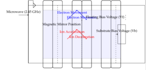
Figure 2 illustrates the pin-on-disk tribometer equipped with a nanoprobe displacement sensor. The overall setup is displayed in Fig. 2, comprising a pin-on-disk tribometer integrated with a nanoprobe displacement sensor. The pin-on-disk tribometer features a rotating platform, a friction beam, and a three-axis (X, Y, Z) manual stage (I). As depicted in Fig. 2, a SiC ball (4 mm radius) is affixed to the free end of the friction beam. Strain gauges on the friction beam measure normal and tangential forces. The specimen is mounted on the rotating platform, which allows positional adjustments. The relative positioning between the SiC ball’s axis and the specimen is controlled by the three-axis manual stage (II)in the X and Y directions, and the normal force is adjusted by a screw bolt in the Z direction. This design maintains the SiC ball horizontally aligned with the friction beam’s axis and the rotating platform’s center, ensuring consistent sliding velocity at each contact point in the tangential direction. Normal load and friction force signals are collected to calculate the friction coefficient.
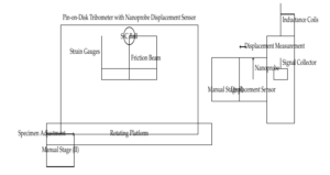
The nanoprobe displacement sensor setup, shown in Fig. 2, includes a displacement sensor with a nanoprobe and a three-axis manual stage (I). The sensor is mounted parallel to the friction beam’s axis, with the probe contacting the SiC ball holder to measure microdisplacements in the tangential direction during friction (refer to Fig. 2). It is important to note that the probe’s contact force for microdisplacement measurement is 0.75 mN, which is significantly smaller than the friction force. The displacement sensor has a measuring range of 350 \(\mu\)m and a resolution of 0.01 \(\mu\)m. Figure 2(d) shows the inductance coils situated inside the rigid support, with a lever arm fixed on the rigid support by a flexible foil and an iron core attached to the lever arm’s end. Two springs regulate the relative positioning of the lever arm and rigid support [10]. Displacement detected by the probe alters the iron core’s insertion length into the inductance coils, changing the magnetic flux. This results in a voltage change collected by the signal collector and recorded. After calibration, the microdisplacement measurements are obtained. In this study, tribological tests are conducted at room temperature and approximately 70% relative humidity, under a normal load of 2 N, with a rotational speed of 180 rpm and a frictional radius of 1.4 mm (with a sliding velocity calculated to be 26 mm/s).
To elucidate the frictional behavior of nanostructured carbon films, TEM images of the low frictional wear tracks of e-NCF and i-CF. The wear track of e-NCF exhibits a slightly less organized nanostructure compared to the originally deposited surface, yet retains its nanocrystalline structure. In contrast, the amorphous structure of i-CF transforms into a nanocrystalline structure containing graphene sheet stacks.
Two widely accepted explanations for the low friction behavior of amorphous carbon films are the formation of a transfer film on the counter sliding surface and the graphitization of the transfer film [12, 19]. The TEM image of the wear track provides direct evidence of structural transformation from amorphous to graphene sheets embedded in the structure during cyclic friction, which we term “graphenization”. This process may contribute to the decrease in friction coefficient.
By comparing the TEM images of e-NCF, i-CF, and their wear tracks, we observe that the wear track of amorphous carbon film in the low friction stage exhibits a similar structure to e-NCF. The tribotest result of i-CF reveals a high friction stage and a gradually-decreasing stage, lasting approximately 1000 frictional cycles, before reaching the low friction stage. To minimize or avoid this high friction stage, we prepared an ion-electron hybrid irradiated film (i/e-NCF), as shown in Fig. 3. The basic structure of i/e-NCF resembles the low friction stage carbon, potentially enabling the film to achieve low friction at an early stage.
The TEM images reveal the nanostructures of the carbon films. Electron irradiation produces a nanocrystalline structure with uniformly distributed graphene sheet stacks, both in-plane and vertically to the substrate. Each stack comprises a few linked graphene sheets with an interplanar spacing of 0.36 nm. Electron diffraction (ED) patterns indicate a more ordered structure. In contrast, ion irradiation yields a pure amorphous structure, while ion-electron hybrid irradiation produces a mainly amorphous film with a 4 nm top layer featuring graphene sheets embedded in the structure after electron irradiation.
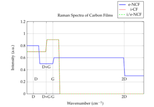
Fig. 3 presents the Raman spectra of the carbon films. The e-NCF spectrum shows distinct D and G bands at 1340 \(cm^{-1}\) and 1600 \(cm^{-1}\), respectively, with a medium-strength 2D band at 2700 \(cm^{-1}\), confirming the presence of graphene sheets. In contrast, the i-CF spectrum exhibits a composite band centered at 1500 \(cm^{-1}\), comprising D and G bands, without a 2D band. The i/e-NCF spectrum shows [insert details]. These results provide insight into the structural properties of the nanostructured carbon films.
The Raman spectra of the carbon films (Figure 3) reveal distinct characteristics. The e-NCF spectrum shows separate D and G bands, but lacks a 2D band. In contrast, the i-CF spectrum exhibits a composite band centered at 1500 \(cm^{-1}\), comprising D and G bands, without a 2D band. The i/e-NCF spectrum shows similar characteristics to i-CF. These differences can be attributed to the growth mechanisms of the graphene sheets. As previously studied [11], the growth mechanism in e-NCF involves inelastic scattering of low-energy electrons, whereas i-CF involves elastic and inelastic collisions between ions and atoms, resulting in sputtering of weakly bonded carbon atoms.
The surface morphologies of the carbon films, produced using different irradiation methods, The AFM image of e-NCF reveals a rough surface with a mean surface roughness (Ra) of 13.42 nm and numerous prominences. In contrast, the surface of i-CF is smoother, with an Ra of 0.087 nm. The surface image of i/e-NCF is similar to i-CF, with a decreased mean surface roughness of 0.08 nm, indicating a change in the top surface to graphene sheets embedded in the structure.
The frictional behaviors of nanostructured carbon films were investigated using a pin-on-disk tribometer with a nanoprobe displacement sensor. The results show that the stabilized low friction coefficient of e-NCF (0.137) is nearly twice higher than that of i-CF (0.075) and i/e-NCF (0.079). The surface roughness of the films plays a crucial role in determining the friction coefficient. The rougher surface of e-NCF (13.42 nm) compared to i-CF (0.087 nm) and i/e-NCF (0.080 nm) may contribute to its higher friction coefficient.
The wear life of the films depends on the interface strength. e-NCF has a shorter wear life (475 cycles) compared to i-CF and i/e-NCF (>2000 cycles). The weaker interface strength of e-NCF is attributed to its lattice-mismatch with the substrate and the random distribution of graphene sheets. In contrast, i-CF and i/e-NCF have stronger interface strengths due to the formation of an interlayer containing Si-Si, C-Si, and C-C bonds.
The ion-electron hybrid irradiation method integrates the merits of smooth surface, high interface strength, and graphene sheets embedded in the nanostructure. i/e-NCFs exhibit excellent frictional properties, good electric conductivity, and magnetic behavior, making them suitable for various applications.
The nanoprobe displacement sensor was used to in-situ monitor the microdisplacement of the SiC ball during friction. The results show that the microdisplacement of e-NCF is larger than those of i-CF and i/e-NCF, which may be caused by its surface roughness. The oscillation amplitude of the microdisplacement can also be quantified, representing the friction-induced oscillation of the pin.
The “graphenization” of NCFs during friction affects the friction coefficient, decreasing it at the early stage. The graphene sheets embedded in the nanostructure play a crucial role in achieving low friction coefficients. The growth mechanism of graphene sheets in e-NCF involves inelastic scattering of low-energy electrons, whereas in i-CF, it involves elastic and inelastic collisions between ions and atoms.
The surface morphology of the films significantly affects their frictional behavior. The rougher surface of e-NCF results in a higher friction coefficient, while the smoother surfaces of i-CF and i/e-NCF lead to lower friction coefficients. The interface strength between the film and substrate also plays a critical role in determining the wear life of the films. The stronger interface strength of i-CF and i/e-NCF contributes to their longer wear life.
The i/e-NCFs exhibit excellent tribological properties, including low friction coefficients and long wear life, making them suitable for various applications. Their good electric conductivity and magnetic behavior further expand their potential uses. The ion-electron hybrid irradiation method offers a promising approach to controlling the frictional behavior of NCFs by integrating the merits of smooth surface, high interface strength, and graphene sheets embedded in the nanostructure.
The interface bonding strength of e-NCF still needs to be improved for further study. Additionally, the effects of different irradiation conditions and film thicknesses on the tribological properties of NCFs warrant further investigation. The nanoprobe displacement sensor provides a valuable tool for in-situ monitoring of microdisplacement during friction, enabling a deeper understanding of the friction mechanism and its relation to surface roughness and interface strength.
In conclusion, this study demonstrates the significant impact of irradiation methods on the tribological properties of nanostructured carbon films. The ion-electron hybrid irradiation method emerges as a promising approach to achieving excellent frictional properties, including low friction coefficients and long wear life. The integration of smooth surface, high interface strength, and graphene sheets embedded in the nanostructure contributes to the superior tribological performance of i/e-NCFs. Furthermore, the nanoprobe displacement sensor provides valuable insights into the friction mechanism, highlighting the importance of surface roughness and interface strength. These findings pave the way for the development of advanced carbon-based coatings with tailored tribological properties for various applications. Future research directions include optimizing irradiation conditions, exploring different film thicknesses, and investigating the effects of interface bonding strength on tribological performance.