
While precise microfluidic flow control can often be achieved along the primary channel path, flow control within corners, side cavities, grooves, and dead-end pores remains difficult due to the need to establish significant and localized circulation at such length scales. As a result of the small scale, microfluidic flows tend to be characterized by a very low Reynolds number and are driven primarily by viscous forces. While pressure gradients will effectively drive flows within the microchannel, they will not efficiently stir the stagnant subregions where streamline topology and molecular diffusion drive mixing and exchange processes. Such behavior is relevant to mixing, particle capturing, pore-scale remediation, and local chemical delivery since the dead-end structures can retain dissolved and suspended material despite continuous flushing of the channel adjacent to them. Recent investigations into small-scale fluid dynamics suggest that the fluid velocity distribution created in small-volume regions depends directly on the surface chemistry, geometry, and electrokinetics of the flow boundaries [1– 4]. Thus, in this paper, the chemically-patterned wall will be considered the source of driving and not just a passive boundary element.
The diffusio-osmosis effect fits this scenario best, as the slip occurs due to solute gradients formed at the surface itself. If a chemical substance is released from or absorbed by the chemically active surface, a corresponding concentration gradient forms. The effect of that substance with the interfacial layer results in the development of a tangential slip velocity along the wall. This fixed-boundary slip phenomenon has the same nature as the diffusiophoretic effect, which occurs because of the same physics of interfacial transport phenomena [5– 9]. In microfluidic applications, the gradients can be used for focusing, entrainment, entrapment of colloidal suspensions in pores, changing of transport in junctions, and maintaining the necessary wall-slip-induced circulation when the pressure-forced exchange becomes weak [10– 16]. For wedge-shaped pores, the gradient field serves as an indication of the solute transport as well as the trigger of the necessary wall slip, creating the corner flow circulation.
Patterned interfacial conditions controlling the direction of microfluidic flows have been extensively researched. Diffusiophoretic banding effects demonstrated the possibility of particle separation in the absence of any external forcing [17]. Electro-osmotic flows structured by surface charge patterns showed the possibility of generating a controlled bulk response to the driving force localized in the interfacial region [18]. The study of catalytic Janus particles and soluto-inertial beacons showed that chemical gradients and asymmetry of geometry and activity can generate long-range directional forces [19, 20]. In this context, the wedge-shaped pore implies that the coated pattern should be analyzed based on the slip and modes induced by the coating, rather than its geometric size.
The role of surface mobility, electrolyte response, zeta potential’s dependence on pH and concentration, solute depletion, and catalyst positioning in diffusio-osmotic phenomena was also recently clarified [21– 25]. Diffusio-osmotic surface-solute measurements provide an opportunity to estimate surface mobility in microchannels [21]. Dead-end channel measurements indicate that pH-dependent zeta potentials may switch the polarity and even amplitude of the particle and wall response [22, 23]. Examples of the CO\(_2\)-driven and salt-driven effects indicate that solute gradients can be achieved in a practical device through chemical driving, without any mechanical pumping [24, 25]. As regards the choice of pore geometries, the design question is to determine where the slip generation should occur such that the flow would persist strongly within the selected wedge while the weakly decaying chemical signature is properly managed.
It should be emphasized that our design problem is related to the active particles’ dynamics and phoretic pumping. Several theoretical papers showed that the combination of nonuniform activity, geometric asymmetry, and confinement is sufficient for creating flows at small surrounding Reynolds numbers [26– 36]. Studies of active pores established that the catalytically active surfaces could pump and mix the fluid, and the direction and amplitude of the motion were determined by geometric or chemical pattern asymmetry [37– 39]. Thus, wedge pore is an interesting geometry as it combines all those ingredients together: the opening angle determines the spectrum of the modes, the radial distance of the sector determines their weights, and the sign of the activity determines their mutual reinforcement or cancellation.
Wedges play an important role due to their natural occurrence in microchannels, porous media, fractured surfaces, and biological systems. Classic papers on corner flow problems demonstrated that a wedge geometry could sustain vortex-like behavior under mechanical forcing, which included Moffatt-type recirculation [40] and scraper-driven flow [41]. Chemical patterning represents an alternative means of actuating corner flows: active surfaces produce chemical concentration gradient, it causes wall slip, and finally, slip leads to Stokes flow. It was recently demonstrated that active wedges may generate flows similar to the ones described for mechanically driven flows [42]. The latter analytical solution requires straightforward physical interpretation in terms of the sector geometry, the range of the slip decay and signed modal balance. Our device selection is based on four characteristic parameters derived from the analytical solution: slip response decay rate, sector sustaining the dominant mode, radial range of slip generation, and critical activity ratio.
The analogous issue emerges in nearby disciplines dealing with transport phenomena at low Reynolds number. Previous work in electro-osmotic and diffusio-osmotic transport has demonstrated the crucial role of patterning and confinement in slip-driven flows [43– 48]. Also research on passive and active mixing has highlighted the importance of matching the size of local recirculation with the dimension of target cavities or pore networks [49, 50]. In case of porous or fractured media, the presence of small corners or dead-end domains as storage volumes makes detrimental the use of an active coating able to produce local recirculation but suffering of a large far-field leakage. Therefore, in addition to the amplitude and location of the local vortices, the current paper focuses on the calculation of response quantities which allow to define the design requirements, namely the angular gain, the screening radius, and the modal balance in the case of paired emitting and absorbing coatings.
The present work poses the following design question: how do the wedge opening angle, the radial position of the sector, and the sign of the catalytic activity affect the circulation, the screening radius, the leakage of the first decaying mode, and the modal balance in a catalytic wedge pore? The answer to this question cannot be inferred from either the total length of the catalytic coating or the total production rate of the solute. Two radially displaced sectors in a wedge might share the same physical length, yet the respective weights in the eigenfunction expansions would differ; similarly, two opposite-signed coatings could be balanced in terms of total flux yet show strong imbalance within the dominant decaying mode. For this reason, the design parameters of angle, radius, and sign are treated as coupled quantities rather than independent geometrical features.
All response quantities considered are calculated based on the same governing equations for the entire process, namely harmonic solute concentration distribution, diffusio-osmotic slip boundary conditions on active walls, and Stokes equation in the interior domain. Within the framework of the log-polar coordinate system, the mode weighting factor turns out to be related to the radial decay; flux moments of finite sectors measure their catalytic activity; angular gain functions describe the amplification of the induced circulation; signed first-mode residuals are used for assessing the extent to which the dominant decaying mode is suppressed; interaction indices evaluate leakage from the near field into the far field; and end-point derivatives indicate the effectiveness of perturbing coating displacements. No additional physical phenomenon is brought into play besides what is already specified within the low-Peclet-number and low-Reynolds-number regime.
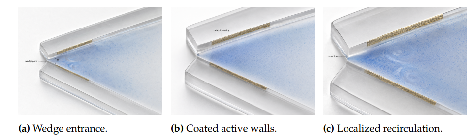
The device-scale view in Figure 1 fixes the physical reading of the problem: catalytic coating is placed on finite wall intervals, solute spreads into the wedge interior, and the induced tangential slip produces a corner-confined recirculation rather than a pressure-driven through-flow. This visual setting matches the mathematical treatment in which wall activity enters through boundary flux and the velocity field enters through a Stokes streamfunction.
Suppose a wedge-shaped geometry in the two-dimensional (\(\rho,\theta\)) polar coordinate system where \(0<\theta<\alpha\). It is possible for the \(\theta = 0\) and \(\theta = \alpha\) boundaries to have catalysts that either produce or consume solute. The deviation from the uniform solute concentration is \(c(\rho,\theta)\) while the velocity vector is represented by \(\mathbf{u}\) and the pressure by \(p\). It is assumed that both solute Peclet number and fluid Reynolds number are so small that diffusion and Stokes equations represent the leading-order phenomena. Under these conditions, the dimensionless concentration and velocity fields satisfy the following relations: \[ \nabla^2 c =0, \label{eq:laplace}\ \tag{1}\] \[\nabla^2\mathbf{u} = \nabla p, \label{eq:stokes}\ \tag{2}\] \[\nabla\cdot\mathbf{u} =0. \label{eq:incompress} \ \tag{3}\] On a chemically active wall, fixed surface activity prescribes the normal concentration gradient. With \(A_0(\rho)\) and \(A_\alpha(\rho)\) denoting the radial activity distributions on the lower and upper walls, respectively, the boundary conditions are written as \[ \frac{1}{\rho}\frac{\partial c}{\partial \theta}(\rho,0) = -A_0(\rho), \label{eq:bc_lower}\ \tag{4}\] \[\frac{1}{\rho}\frac{\partial c}{\partial \theta}(\rho,\alpha) = A_\alpha(\rho). \label{eq:bc_upper} \ \tag{5}\] The diffusio-osmotic slip velocity is proportional to the tangential concentration gradient. For constant dimensionless surface mobility \(M\), the radial slip on either wall is \[u_s(\rho)=M\left.\frac{\partial c}{\partial \rho}\right|_{S}, \label{eq:slip} \tag{6}\] where \(S\) indicates the wall on which the gradient is evaluated. The incompressible two-dimensional flow is represented by a streamfunction \(\Psi\) such that \[u_\rho=\frac{1}{\rho}\frac{\partial \Psi}{\partial \theta}, \qquad u_\theta=-\frac{\partial \Psi}{\partial \rho}.\label{eq:streamdef} \tag{7}\] The streamfunction satisfies the biharmonic equation, \[\nabla^4\Psi=0,\label{eq:biharmonic} \tag{8}\] with no penetration and prescribed slip on the wedge walls. Eqs. (1)–(8) define the physical setting used throughout the response calculation.
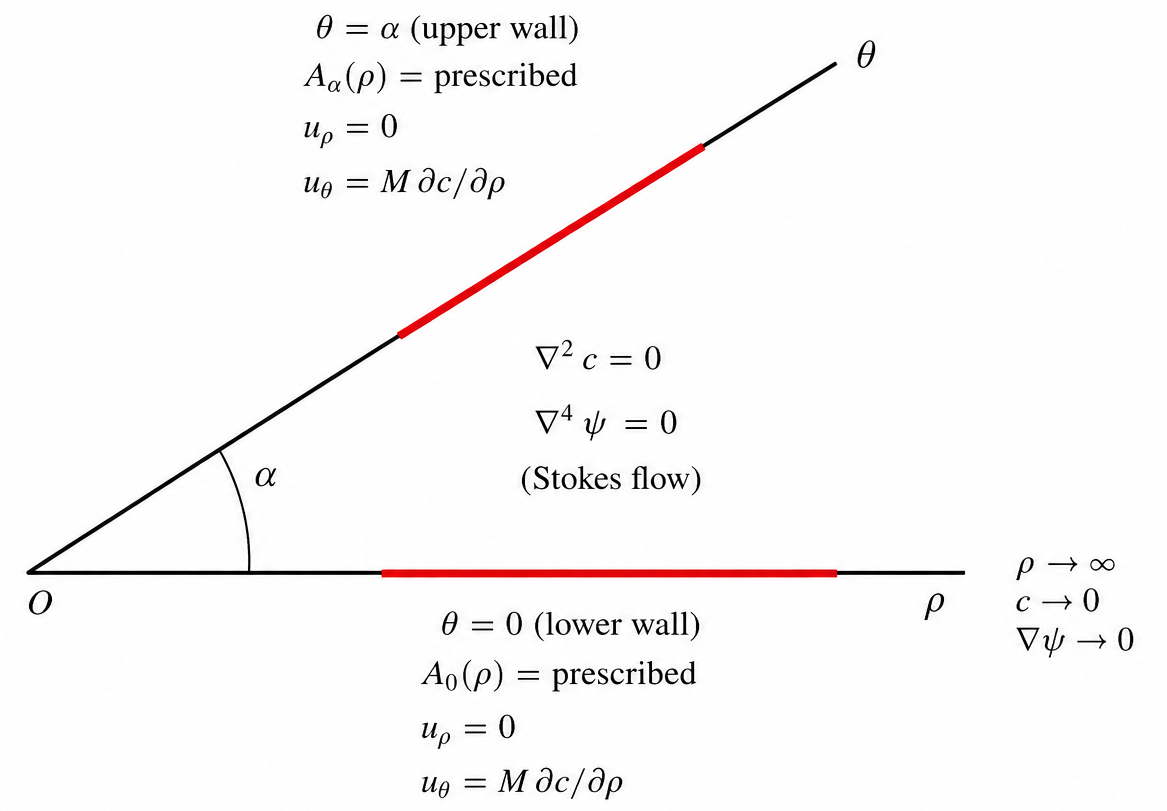
The coupling relations of Figure 2 link concentration and motion through an equation system devoid of a body force. The harmonic solute potential defines the wall gradient tangential to the surface, which in turn dictates the slip associated with the biharmonic stream function solution. The wedge dynamics are thus governed by wall chemistry and geometry rather than pressure driving.
The geometry catalog shown in Table 1 gives the angle of the wedges, catalytic regions, sign of wall activity, and wall class used in the calculation. These geometries correspond to the catalytic wedge geometries investigated by Nowak and Lisicki [42]. These geometries are mapped from the Nowak and Lisicki catalog into the standard form suitable for the response matrix construction. These include one-wall, two-wall, finite active region/absorbing boundary, reflector sectors, and two-wall patches in flux balance near the vertex.
| Case | Opening angle | Active interval(s) | Boundary class | Configuration represented in the calculation |
| U1 | \(\pi/4,\ \pi/2,\ 3\pi/4\) | uniform lower wall | one active wall, opposite no-slip hydrodynamic wall | Angular response of one-wall slip forcing. |
| U2 | \(\pi/4,\ \pi/2,\ 3\pi/4\) | uniform lower and upper walls | two active walls | Symmetric slip forcing with counterflow along the wedge bisector. |
| A1 | \(\pi/6\) | \((a,b)=(1,3)\) | active lower wall, absorbing upper wall | Finite catalytic sector displaced away from the corner. |
| A2 | \(\pi/6\) | \((a,b)=(0,3)\) | active lower wall, absorbing upper wall | Catalytic sector starting at the wedge vertex. |
| A3 | \(\pi/6\) | \((a,b)=(1,\infty)\) | active lower wall, absorbing upper wall | Semi-infinite catalytic sector used as a limiting case. |
| R1 | \(4\pi/7\) | \((0.5,1.5)\) and \((2.5,3.5)\) on each wall | reflective walls with paired positive/negative sectors | Multi-sector pattern for evaluating near–far sector dominance. |
| R2 | \(3\pi/7\) | \((0.5,1.5)\) and \((2.5,3.5)\) on each wall | reflective walls with paired positive/negative sectors | Narrower multi-sector pattern for evaluating radial concentration of activity. |
| F1 | \(\pi/3\) | \((0,1)\) on both walls | lower emitting, upper absorbing | Tip-supported two-wall actuation with two counter-rotating eddy regions. |
| F2 | \(\pi/2\) | \((0,1)\) on both walls | lower emitting, upper absorbing | Right-angle finite-corner configuration with one compact vortical region. |
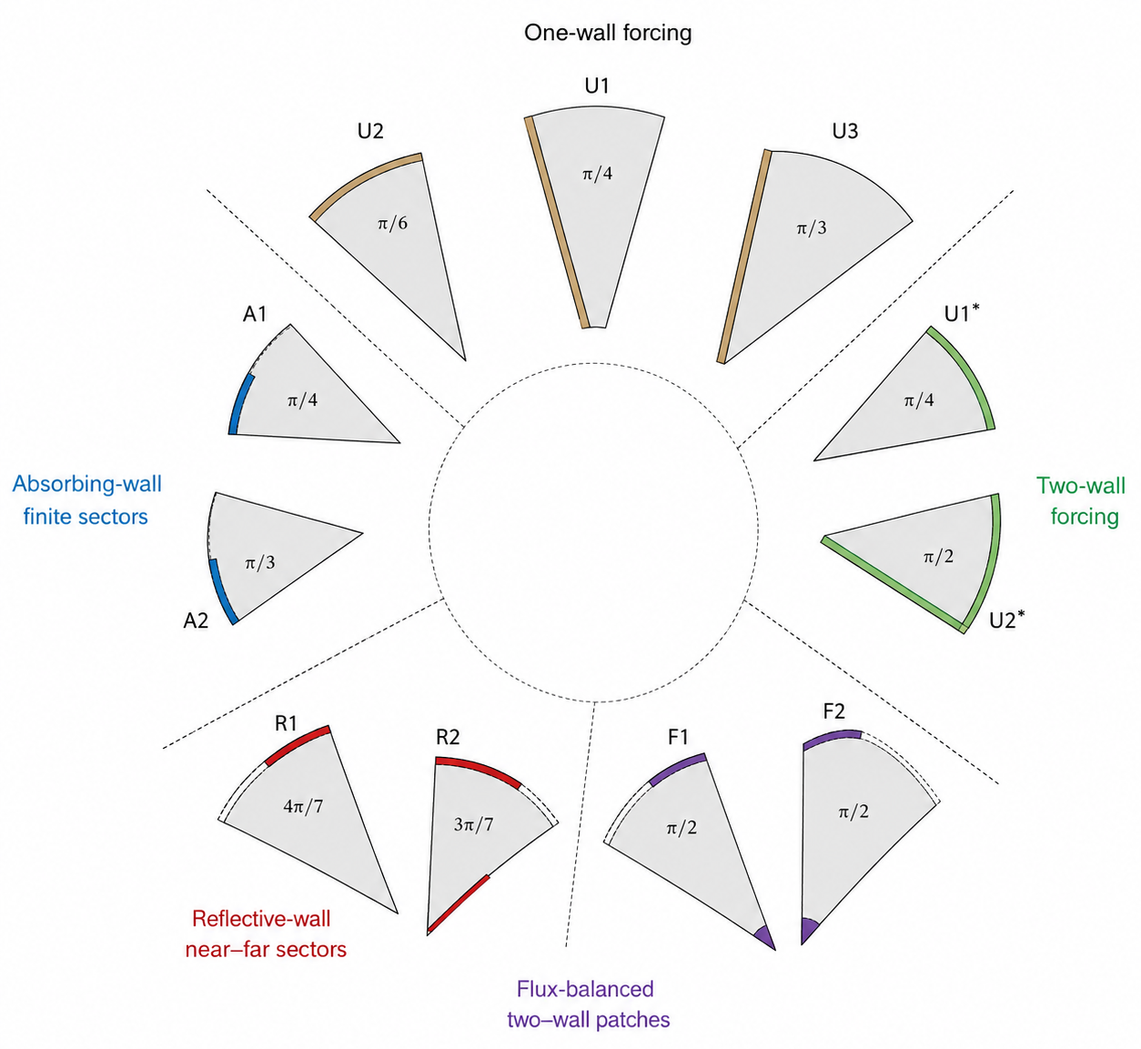
The graphic representation of the case map as depicted in Figure 3 also demonstrates that the calculation includes variations of angular dependency as well as radial pattern dependency. This is crucial because wedge opening affects the eigenvalue spectrum while active sector location affects the modal moment.
The first step in the response calculation is the transformation of the radial axis into \[x=\ln\left(\frac{\rho}{b_*}\right),\label{eq:logcoord} \tag{9}\] where \(b_*\) is the largest finite radial extent of the active sectors in a given case. Under this transformation, \[\rho^2\nabla^2 c = \frac{\partial^2 c}{\partial x^2}+\frac{\partial^2 c}{\partial \theta^2}.\label{eq:rectlaplace} \tag{10}\] The wedge diffusion problem can thus be reformulated as a harmonic problem for the rectangle \((x,\theta)\in(-\infty,\infty)\times(0,\alpha)\) with an advantage in that decay in the radial direction is expressed as decay in the \(x\) coordinate, whereas decay in the angular direction manifests itself as a discrete eigenvalue condition. Rather than constructing the entire concentration field, the response approach retains the lowest decay mode, which is the one determining the long-range influence of a catalytic configuration of finite extent.
For a reacting wall and a reflecting wall, the dominant exponent of decay is \[\lambda_D=\frac{\pi}{2\alpha}.\label{eq:lambdad} \tag{11}\] For flux-balanced reflective or two-wall finite patterns, the constant-flux mode is removed by conservation and the dominant nonzero mode is \[\lambda_N=\frac{\pi}{\alpha}.\label{eq:lambdan} \tag{12}\] The corresponding slip decay exponent is one larger than the concentration decay exponent because slip contains a radial derivative: \[m=\lambda_1+1, \qquad \lambda_1\in\{\lambda_D,\lambda_N\}.\label{eq:slip_exp} \tag{13}\] Thus, for a finite flux-balanced pattern with largest active-sector radius \(b_*\), \[\left|\frac{u_s(\rho)}{u_s(b_*)}\right|\approx \left(\frac{b_*}{\rho}\right)^{m}.\label{eq:screening_decay} \tag{14}\] Eq. (14) provides a direct screening quantity. The radius at which the slip magnitude falls to a fraction \(\varepsilon\) of its value at \(b_*\) is \[\frac{\rho_\varepsilon}{b_*}=\varepsilon^{-1/m}.\label{eq:screenradius} \tag{15}\] This quantity is not a streamline solver; it is a design-level predictor of how far chemically generated wall forcing should remain dynamically relevant.
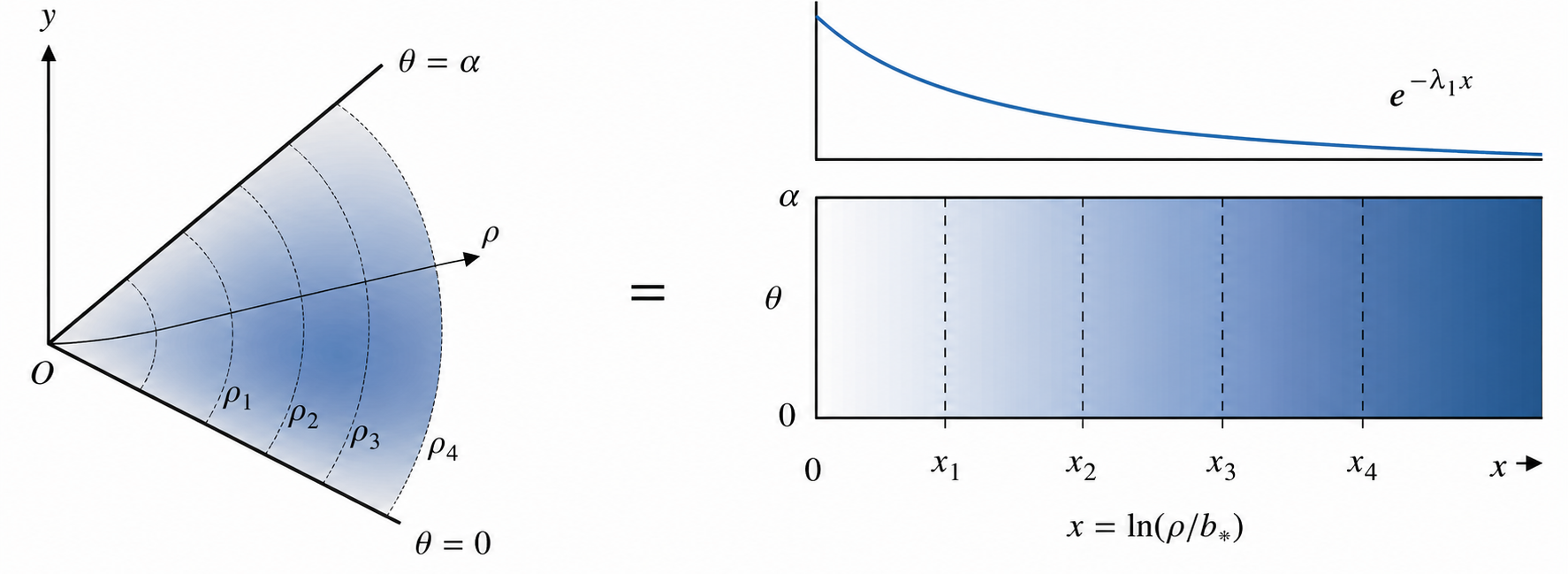
The map shown in Figure 4 clarifies why the placement of sectors cannot be assessed on the basis of physical distance alone. With the radial coordinate linearized, an outward shift alters the mode weight of the sector via its moment and hence affects its far-field slip pattern.
The individual active sectors are characterized by their flux moments. For an active sector with constant activity \(A_j\) running from \(a_j\) to \(b_j\), the moment associated with the first mode is \[\mathcal{M}_{\lambda_1}^{(j)} = A_j \int_{a_j}^{b_j} \rho^{\lambda_1}\,d\rho = A_j\frac{b_j^{\lambda_1+1}-a_j^{\lambda_1+1}}{\lambda_1+1}.\label{eq:moment} \tag{16}\] The absolute moment measures how strongly a patch projects onto the dominant wedge mode. For two finite sectors with the same absolute activity, the near–far dominance ratio is \[\Xi_{\mathrm{far/near}}= \frac{|b_f^{\lambda_1+1}-a_f^{\lambda_1+1}|} {|b_n^{\lambda_1+1}-a_n^{\lambda_1+1}|}. \label{eq:dominance} \tag{17}\] A value larger than unity indicates that the farther sector controls the leading far-field concentration and slip signature more strongly than the near sector. This is especially important in wedge pores because the power \(\lambda_1+1\) increases as the wedge narrows, so radial placement can outweigh sector length.
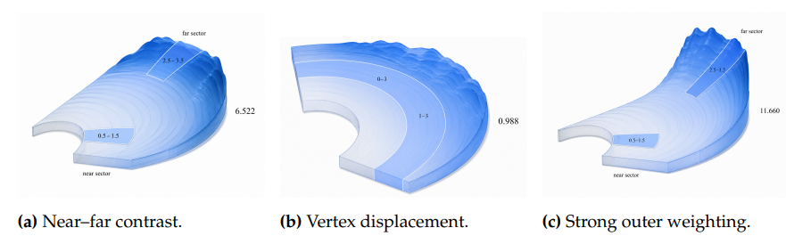
The landscapes in Figure 5 clarify the dominance ratios in the results. Even when two sectors have identical physical length and equal activity magnitude, the far sector can control the leading mode because the first modal moment weights the outer endpoint more heavily.
Uniform wall actuation is evaluated by an angular gain calculation. If the streamfunction takes the separable form \[\Psi(\rho,\theta)=U\rho F(\theta),\label{eq:sepstream} \tag{18}\] then the dimensionless angular gain is defined as \[G_\Psi(\alpha)=\max_{0\leq\theta\leq\alpha}|F(\theta)|.\label{eq:gain} \tag{19}\] For one active wall, the angular response function used here is \[F_1(\theta;\alpha)=\frac{\alpha(\alpha-\theta)\sin\theta-\theta\sin\alpha\sin(\alpha-\theta)}{\alpha^2-\sin^2\alpha}. \label{eq:f1} \tag{20}\] For two active walls, the corresponding symmetric response is \[F_2(\theta;\alpha)=\frac{(\alpha-\theta)\sin\theta-\theta\sin(\alpha-\theta)}{\alpha-\sin\alpha}. \label{eq:f2} \tag{21}\] The values of \(G_\Psi\), \(\theta_{\max}/\alpha\), average gain magnitude \(\langle |F|\rangle\), and RMS gain \(\langle F^2\rangle^{1/2}\) were obtained through dense quadrature over angles. These provide a means to quantify the strength and location angle of the induced vorticity field without the need to plot the full velocity distribution.
The value of the sectoral moment in Eq. (16) is always positive because of the goal to quantify the strength of finite sectors. But, the cancellation occurs based on the sign of the activity itself. For a set of sectors with activity signs \(s_j\in\{-1,+1\}\) and absolute moment magnitudes \(|\mathcal{M}_{\lambda_1}^{(j)}|\), the normalized signed modal residual is defined as \[\mathcal{B}_{\lambda_1}=\frac{\left|\sum_{j=1}^{N}s_j|\mathcal{M}_{\lambda_1}^{(j)}|\right|}{\sum_{j=1}^{N}|\mathcal{M}_{\lambda_1}^{(j)}|}. \label{eq:signedbalance} \tag{22}\] A value of zero indicates first-mode cancellation, whereas a value close to unity indicates that one sign dominates the leading response. For a near–far pair of equal physical length and opposite sign, the far-sector activity magnitude needed to cancel the near-sector first mode is \[\chi_{f/n}^{\mathrm{cancel}}=\frac{|A_f|}{|A_n|}=\frac{|\mathcal{M}_{\lambda_1}^{(n)}|}{|\mathcal{M}_{\lambda_1}^{(f)}|}=\Xi_{\mathrm{far/near}}^{-1}. \label{eq:cancelcontrast} \tag{23}\] This distinction distinguishes chemical flux balance from modal balance. Two sectors may have equal and opposite total activity but still leave a large first-mode residual if they occupy different radial positions.
The decay law in Eq. (14) also gives a pairwise estimate of radial interaction. Let \(r_i=(a_i+b_i)/2\) and \(r_j=(a_j+b_j)/2\) be the sector centroids, with \(r_j>r_i\). The surviving fraction of the slip generated near \(r_i\) when observed near \(r_j\) is approximated by \[\Gamma_{i\rightarrow j}=\left(\frac{r_i}{r_j}\right)^m. \label{eq:interactionindex} \tag{24}\] This index is intentionally local and directional. It evaluates outward leakage of a finite-sector response and is therefore most useful for estimating whether an inner catalytic feature is likely to influence a farther feature in the same wedge.
To identify which geometric adjustment most efficiently changes the modal response, the first-mode moment is differentiated with respect to the sector endpoints. For constant activity, \[\frac{\partial \mathcal{M}_{\lambda_1}}{\partial b}=A b^{\lambda_1},\qquad \frac{\partial \mathcal{M}_{\lambda_1}}{\partial a}=-A a^{\lambda_1}. \label{eq:edge_sens} \tag{25}\] If a sector is translated outward by a small distance while its physical length is held fixed, both endpoints move by the same increment and \[\frac{d\mathcal{M}_{\lambda_1}}{d\delta}=A\left(b^{\lambda_1}-a^{\lambda_1}\right). \label{eq:translation_derivative} \tag{26}\] The dimensionless translation leverage is defined as \[\mathcal{L}_{\tau}=\frac{r_c}{\mathcal{M}_{\lambda_1}}\frac{d\mathcal{M}_{\lambda_1}}{d\delta},\qquad r_c=\frac{a+b}{2}. \label{eq:translation_leverage} \tag{27}\] This quantity measures the fractional gain in first-mode strength caused by a fractional outward displacement of the sector centroid. It is included because a sector of unchanged length can become substantially more influential solely by being moved away from the vertex.
Angular-gain functions have been calculated on uniform meshes of \(\theta/\alpha\) such that the position and value of \(\max |F|\) result from the function rather than the sampling frequency. Sectoral moments, cancellation ratios, interaction indices, and translation sensitivities have been directly evaluated from the analytical formulas given above. Two internal checks were performed. Endpoint derivatives from Eq. (25) have been checked against a second-order centered finite difference approximation of the sectoral moment from Eq. (16). This ensures the consistency between the leverage values from the same wedge exponent and sector geometry that enters the dominance ratio definition. In addition, the screening radius has been recalculated according to the normalized slip law in Eq. (15) – the screening radii reported in Table 3 therefore correspond to 5% and 1% threshold levels of attenuated gains. With these two internal checks, all the design parameters for any given wedge geometry are obtained consistently.
The normalization procedure makes all the design parameters independent of the activity unit. Scaling up the catalytic strengths by a common multiplicative constant affects only the dimensionless slip, without changing \(G_\Psi\), \(\Xi_{\mathrm{far/near}}\), \(\mathcal{B}_{\lambda_1}\), \(\chi_{f/n}^{\mathrm{cancel}}\), \(\Gamma_{i\rightarrow j}\), and \(\mathcal{L}_{\tau}\). It follows that all tables below describe geometry–activity maps; namely, what geometric sector/angle/polarization sign combination is preferable before specifying mobility and reaction rate constants for specific materials.
Table 2 contains the angular gain quantities associated with uniform actuation on one or two walls. As \(\alpha\) increases for uniform actuation on one wall, the quantity \(G_\Psi\) exhibits monotonically increasing behavior as follows: \(G_\Psi=0.119\) at \(\alpha=\pi/4\), \(0.252\) at \(\alpha=\pi/2\), and \(0.409\) at \(\alpha=3\pi/4\). The same type of monotonically increasing behavior is observed for uniform actuation on two walls; however, the angular gains are smaller for this case due to the symmetry of forcing, since counterflows exist along the wedge bisectors due to the symmetrical forcing. Angular gains for two walls range between \(0.076\) and \(0.249\). The opening angle therefore acts as an angular amplifier: it changes the cross-sectional region over which slip-driven circulation can develop while leaving the wall-forcing normalization fixed.
| Case | \(\alpha/\pi\) | \(G_\Psi=\max|F|\) | \(\theta_{\max}/\alpha\) | \(\langle |F|\rangle\) | \(\langle F^2\rangle^{1/2}\) |
|---|---|---|---|---|---|
| one active wall | 0.25 | 0.119 | 0.336 | 0.067 | 0.078 |
| one active wall | 0.50 | 0.252 | 0.344 | 0.141 | 0.166 |
| one active wall | 0.75 | 0.409 | 0.353 | 0.228 | 0.268 |
| two active walls | 0.25 | 0.076 | 0.212 | 0.050 | 0.055 |
| two active walls | 0.50 | 0.158 | 0.215 | 0.102 | 0.113 |
| two active walls | 0.75 | 0.249 | 0.220 | 0.162 | 0.178 |
In addition, mean and root-mean-square gains are presented, both of which are crucial for distinguishing between a sharply peaked local flow feature and an extended area of increased circulation. In both series of computations, these averaged quantities grow with opening angle, implying that the wedge effect is not just about displacement, but it actually makes the cavity better at sustaining slip-induced flows. Indeed, this agrees with results of mixing studies at low Reynolds numbers, where the geometry of access becomes more important than the inertial forcing [49, 50].
Information about the angular position of the gain maximum also proves to be valuable. For the one-wall cases, it happens at \(\approx 0.34\alpha – 0.35\alpha\), implying that the strongest streamfunction response occurs in the fluid, although relatively close to the active wall. In the two-wall scenarios, on the other hand, the peak shifts much closer to the walls to \(\approx 0.21\alpha – 0.22\alpha\). Furthermore, there also emerges another identical peak in the vicinity of the opposite wall. This implies the necessity for a wall-attached flow that reverses directions along the way. Note also that the gain averaging follows the same hierarchy as the gain maximum. That is, larger opening angles make the wedge better at inducing angular circulation; hence, wider wedges not only produce localized peaks, but elevate angular averages of induced circulation. The difference in gains due to one- and two-wall forcing thus cannot be simply explained by decreased forcing strength in the former case. Instead, this comes from the fact that in one-wall problems the induced circulation is dominated by a single lobe attached to the active wall, while two walls cause it to separate into several lobes.
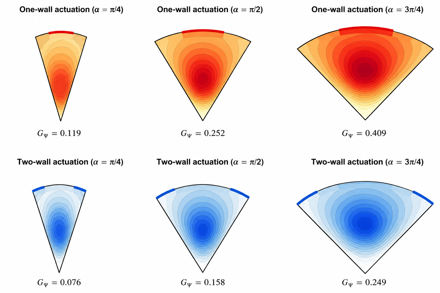
This visual difference between the wedges in Figure 6 helps us understand why maximum gain alone is inadequate for characterizing the response behavior. The single-walled configuration concentrates the high-amplitude lobe toward the active wall and away from the origin as the wedge expands, whereas the double-walled configuration splits the amplitude into two smaller lobes located near the walls. From Table 2, then, it becomes clear why wide wedges yield higher gain and why two-walls force produces lower maximum gain compared to one-wall forcing.
The distribution of response lobes shown in Figure 6 demonstrates how angular gain is a geometrical phenomenon, rather than the result of having larger coated lengths. Increased values of \(\alpha\) provide greater angular space for creating the streamfunction peak, whereas two-walls symmetric forcing will always be weaker since it spreads out the circulation by wall motions in opposite directions.
The decay laws in Eqs. (13)–(15) were applied to the finite active-sector cases. The dominant concentration exponent \(\lambda_1\), the slip exponent \(m\), and the radii at which wall slip is predicted to fall to 5% and 1% of its value at the largest finite patch radius are listed in Table 3. These quantities translate the spectral structure of the wedge into a physical spacing rule for patterned microchannels.
| Case | Boundary class | \(\alpha/\pi\) | \(\lambda_1\) | \(m=\lambda_1+1\) | \(\rho_5\%/b_*\) | \(\rho_1\%/b_*\) |
| A1–A2 | absorbing upper wall | 0.167 | 3.000 | 4.000 | 2.115 | 3.162 |
| F1 | flux-balanced two-wall patch | 0.333 | 3.000 | 4.000 | 2.115 | 3.162 |
| F2 | flux-balanced right-angle patch | 0.500 | 2.000 | 3.000 | 2.714 | 4.642 |
| R1 | reflective multi-sector | 0.571 | 1.750 | 2.750 | 2.972 | 5.337 |
| R2 | reflective multi-sector | 0.429 | 2.333 | 3.333 | 2.456 | 3.981 |
The values indicate a high degree of localization for narrow absorbing geometries. For \(\alpha=\pi/6\), the active-sector geometries have \(m=4\), meaning a radial increase of ten times compared to \(b_*\) results in suppression of slip by four orders of magnitude. The same exponent applies to the \(\alpha=\pi/3\) flux-balanced two-wall patch, since the conservation law eliminates the zero mode and thus makes \(\lambda_N=3\). Right angle corresponds to \(m=3\), a lower value yet high enough to ensure that the dominant slip contribution occurs over just a few patch sizes. This prediction is crucial when considering microchannels with finite-length corners: if active corners are located at a distance of \(3b_*\) or more away from each other, their leading slip contributions are practically diminished to \(5\)% in right angles.
Two reflective multi-sector wedges illustrate how the localization depends on opening angle. Decrease of \(\alpha\) from \(4\pi/7\) to \(3\pi/7\) leads to a rise of \(\lambda_1\) from 1.750 to 2.333 and hence to contraction of the \(5\)% screening distance from \(2.97b_*\) to \(2.46b_*\). Hence, narrower reflective wedge provides stronger localization, while wider reflective wedge offers increased activity influence over a larger radial vicinity. Numerically, the difference becomes clear from the following geometrical criterion: tuning of wedge angle leads to localization regardless of the fixed patch length and patch activity.
A further consideration of the \(1\)% values reinforces the conclusion. Slip screening envelope calculated for right-angle finite patch yields \(\rho_{1\%}/b_*=4.642\), while for narrower and equally active patches it is equal to \(3.162\). For an array of active dead-end pores, such difference becomes essential and defines whether the adjacent corner will experience only a small residual slip or suffer some chemical disturbance due to its neighbor. Thus, the calculation highlights a distinction between two design purposes that might get intertwined: choosing a geometry that maximizes vortex formation and selecting one minimizing interference between active spots. Consistency in choosing wedge and flux properties would be required for achieving both objectives.
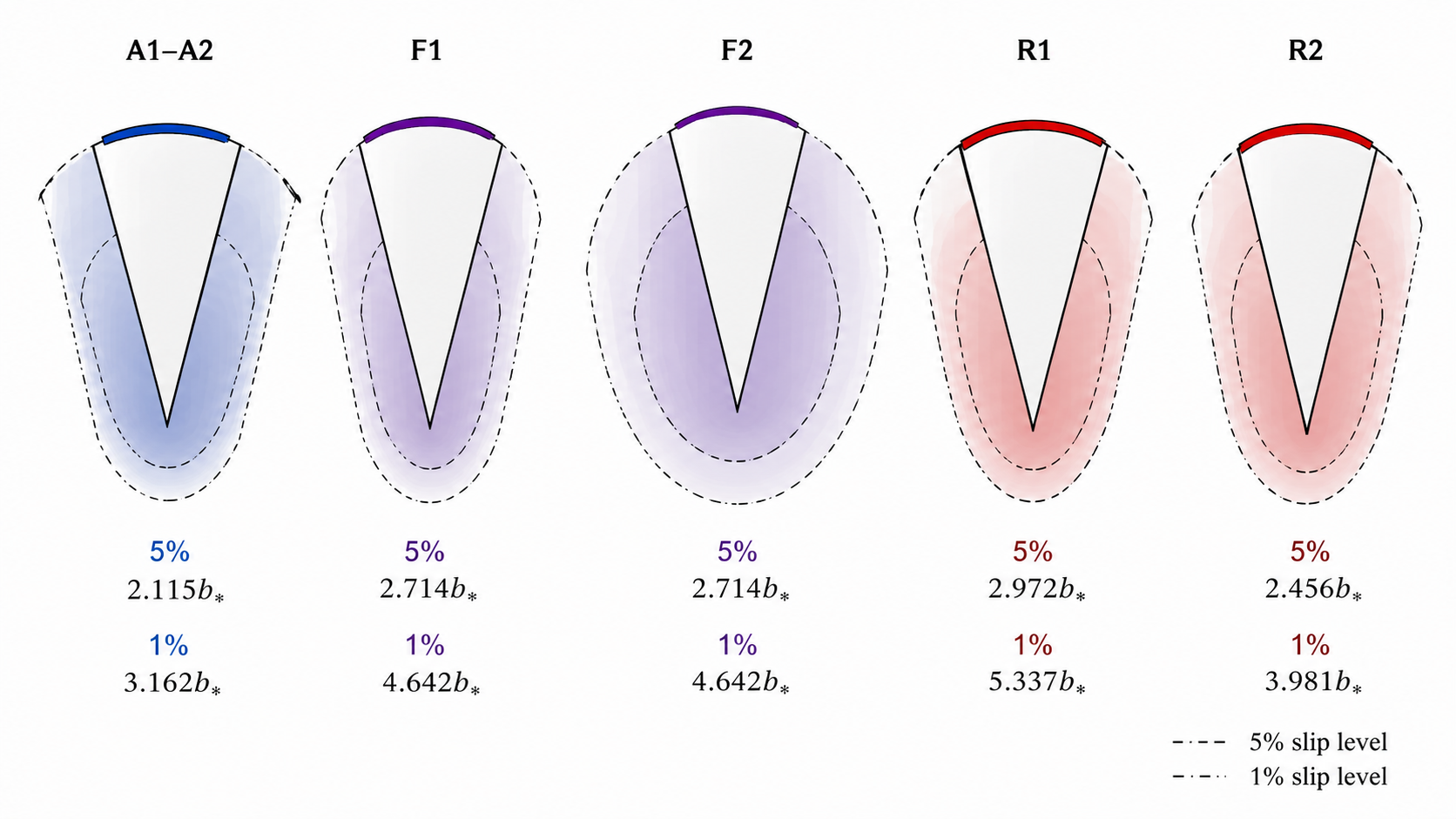
The envelopes in Figure 7 interpret the power-law exponent into an effective distance metric. In designing a device, one could use the envelope associated with 5% screening to determine the separation where the adjacent corner would receive a marginal influence from the finite activity region. While the conservative 1% envelope is appropriate when placing several active corners within the same channel network. The gap between F2 and R2 is another confirmation that the choice of wedge angle and boundary condition cannot be compensated by the outer radius alone.
From the attenuation envelopes shown in Figure 7, the localized property is readily apparent. While the flux-balanced right-angle finite design exhibits a tight 5% reach at \(2.714b_*\), the two reflective multi-sectors have longer reaches in terms of the distance when the wedge exponent is lower.
Moreover, the analysis of screening data can reveal whether the finite corner acts as a local pump or a global actuator. While the flux-balanced right-angle design presents a short practical range of influence, the narrow reflective geometry screens fast in comparison to the sector size. Hence, the former can serve as building blocks for dense arrays, whereas the latter must carefully consider the effect of modal leakage.
Finally, the analysis of modal weight dependence on radial position is carried out. The results of comparing near and far sectors for the two reflective multi-sectors as well as the displaced finite sector \((1,3)\) and the sector attached to the vertex \((0,3)\) in the absorbing \(\pi/6\) wedge are tabulated in Table 4. This comparison is needed because two sectors with similar physical lengths can project very differently onto the first decaying mode.
| Case | \(\alpha/\pi\) | \(\lambda_1\) | Compared sectors | Dominance ratio | Interpretation |
| R1 | 0.571 | 1.750 | \((2.5,3.5)/(0.5,1.5)\) | 6.522 | far sector controls the first mode |
| R2 | 0.429 | 2.333 | \((2.5,3.5)/(0.5,1.5)\) | 11.660 | far-sector control strengthens in narrower wedge |
| A1/A2 | 0.167 | 3.000 | \((1,3)/(0,3)\) | 0.988 | the missing inner unit contributes little to the first mode |
Large dominance ratios for the far sector are due to weighting by \(\rho^{\lambda_1}\) in Eq. (16). At \(\alpha=4\pi/7\), the sector in \((2.5,3.5)\) has 6.52 times greater contribution to the first mode than that of \((0.5,1.5)\). For \(\alpha=3\pi/7\), the dominance ratio is 11.66 due to the increased exponent. The physical meaning of this is that the outer sector may be the dominant factor for the large-scale chemical distribution although being farther from the corner tip. Hence, a catalyst placed close to the corner creates a strong circulation effect locally, but not necessarily a strong control effect for far-field concentrations and slip responses.
Absorption of a narrow wedge of width \(\pi/6\) explains why excision of \((0,1)\) from a wedge ending at \(b=3\) results in little change in the leading moment. With \(\lambda_1=3\), the moment depends upon \(b^4-a^4\). The interval \((0,1)\) contributes only \(1/81\) to the full moment, hence the wedge \((1,3)\) retains \(98.8\%\) of the leading mode moment. One may think intuitively that since the latter wedge has two-thirds of the length of the former, its weight should be correspondingly less. However, as shown above, most of the mode moment is located in the outer part of the wedge, thus \((1,3)\) is very close in weight to \((0,3)\). From an engineering point of view, such a solution means that avoiding the very immediate vicinity of the corner may allow retaining near the same far-field actuation signal while reducing the fabrication efforts or freeing the corner for other functionality.
Comparison of the ratios of dominance in Table 4 reveals that the radius dependence is essential in first-mode control, even when there appear to be comparable physical lengths in catalytic coatings. The most pronounced difference occurs for the reflective narrow wedge where the largest power-law exponent makes the farther sector dominate. The near equality of \((1,3)\) and \((0,3)\) sectors additionally confirms the conclusion about the high efficacy of shortened sectors avoiding the inner vicinity of the vertex. Indeed, the sector \((1,3)\) is about two-thirds of the physical length of \((0,3)\), but contains almost all the modal weight owing to the high first-mode radius dependence.
Calculation of signed modal closure showed that in both pairs of reflected near and far sectors, equal strength does not lead to equal modes. In particular, in the case of \(\alpha=4\pi/7\), a pair of equal strengths gives rise to a residual of 0.734, whereas for \(\alpha=3\pi/7\) this number increases to 0.842 owing to a larger power-law exponent. Hence, cancelation is impossible without an explicit activity contrast. Specifically, the farther sector must have an activity coefficient smaller than the activity of the near sector by a factor of 0.153 for the reflective wide wedge and 0.086 for the reflective narrow wedge.
| Case | \(\lambda_1\) | \(\Xi_{\mathrm{far/near}}\) | \(\mathcal{B}_{\lambda_1}\) for equal \(|A|\) | \(\chi_{f/n}^{\mathrm{cancel}}\) | \(\Gamma_{n\rightarrow f}\) |
|---|---|---|---|---|---|
| R1, \(\alpha=4\pi/7\) | 1.750 | 6.522 | 0.734 | 0.153 | 0.049 |
| R2, \(\alpha=3\pi/7\) | 2.333 | 11.660 | 0.842 | 0.086 | 0.026 |
The radial interaction index emphasizes this understanding, with only 4.9% of the near sector slip signal remaining at the far sector centroid location in R1 and only 2.6% remaining in R2. In other words, the near sector has relatively little influence beyond its immediate neighborhood, while the far sector influences the slowly varying chemical signature. The physical consequence of such an imbalance is that the near sector drives the nearby vortex, while the far sector governs the slowly decreasing signal. It is clear that simple cancellation of total activity is inadequate; what is needed is balance in the signed modal moment, as shown by the relative ratios in Table 5.
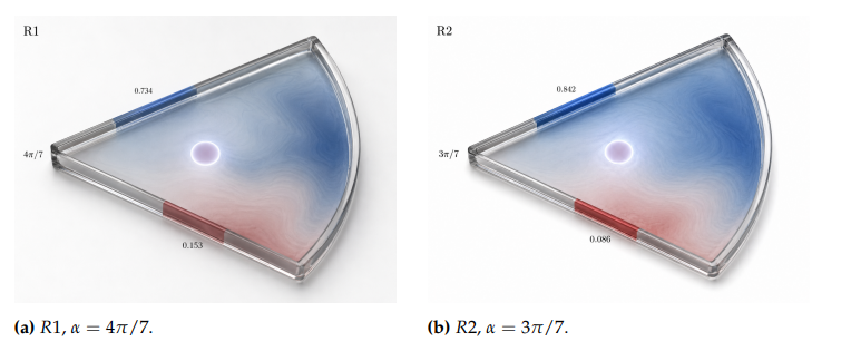
The signed-sector views in Figure 8 illustrate the distinction between flux cancellation and modal cancellation. Equal physical lengths with opposite signs do not eliminate the dominant mode because the outer sector carries greater radial moment weight.
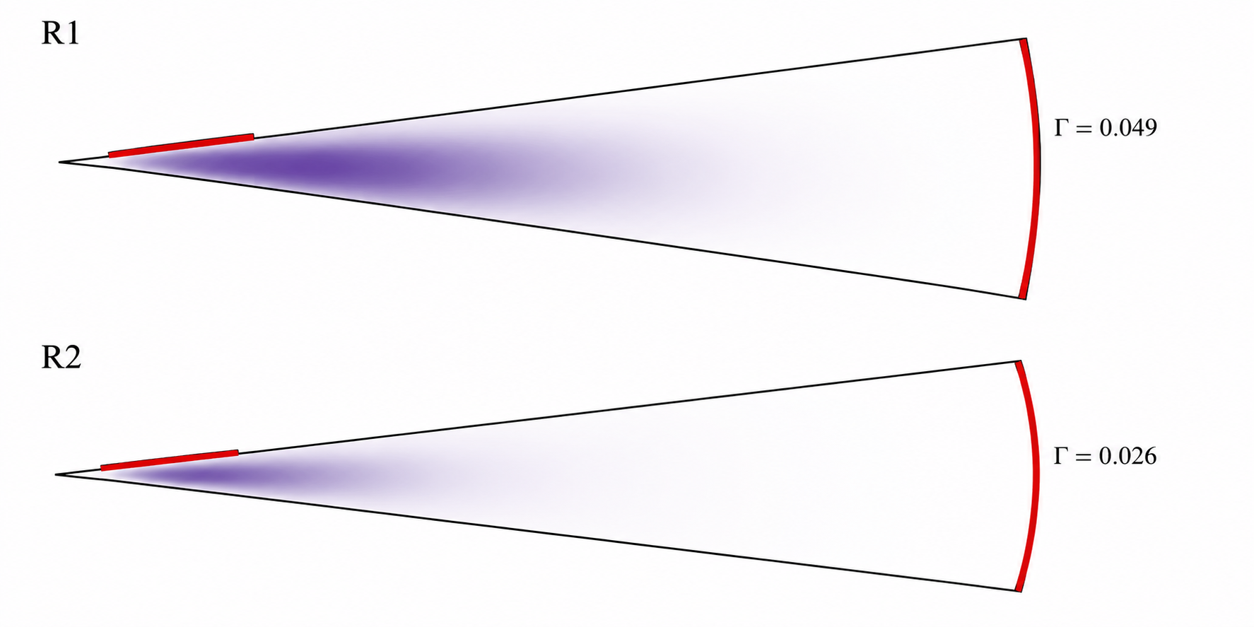
The local fields in Figure 9 make clear why the requirements for the local and far-field designs differ. The near patch could create an observable local effect while providing a negligible portion of its slip field at the radius of interest compared to the far patch.
Both the residual and interaction indices must be analyzed in combination. High residual indicates imbalance in the signed moment, while a low interaction index indicates that the inner sector has low contribution to the neighborhood around the far sector. As such, the two reflection cases reveal the same physical imbalance from two angles: outer sector activities dictate the signature of the modes, while inner sector activities remain local.
The derivative sensitivities with respect to endpoint in Eq. (25) were calculated for representative finite sectors. The outer endpoint will have the larger positive leverage as \(b^{\lambda_1}>a^{\lambda_1}\); however, this dependence depends on both the wedge angle and the sector location. The first mode moment \(\mathcal{M}_1\) and the translation leverage \(\mathcal{L}_{\tau}\) for each type of sector considered in the paper are listed in Table 6.
| Configuration | Interval | \(\lambda_1\) | \(|\mathcal{M}_{\lambda_1}|/|A|\) | \(\mathcal{L}_{\tau}\) |
|---|---|---|---|---|
| R1 near sector | \((0.5,1.5)\) | 1.750 | 1.055 | 1.645 |
| R1 far sector | \((2.5,3.5)\) | 1.750 | 6.880 | 1.738 |
| R2 near sector | \((0.5,1.5)\) | 2.333 | 1.129 | 2.105 |
| R2 far sector | \((2.5,3.5)\) | 2.333 | 13.167 | 2.305 |
| A1 displaced sector | \((1,3)\) | 3.000 | 20.000 | 2.600 |
| A2 vertex sector | \((0,3)\) | 3.000 | 20.250 | 2.000 |
| F2 tip sector | \((0,1)\) | 2.000 | 0.333 | 1.500 |
The reason behind this phenomenon lies in the sensitivities. The lost unit interval gives very little to the first mode moment, since the moment itself scales with \(\rho^3\) before integration. Furthermore, the displaced sector has higher translation leverage, \(\mathcal{L}_{\tau}=2.600\), compared to the vertex-attached sector, \(\mathcal{L}_{\tau}=2.000\). Thus, a minor displacement of the segment becomes more significant after its removal from the tip. The reflective conditions increase both near and far sector translation leverage with narrowing of the wedge, further confirming the high sensitivity of narrow wedges to their radial position. Sensitivity to the outer edge tolerance implies that for lithographically or printed catalytic coatings tolerances are more crucial at the outer radius, not the inner radius, of a finite sector in particular for high wedge exponents.
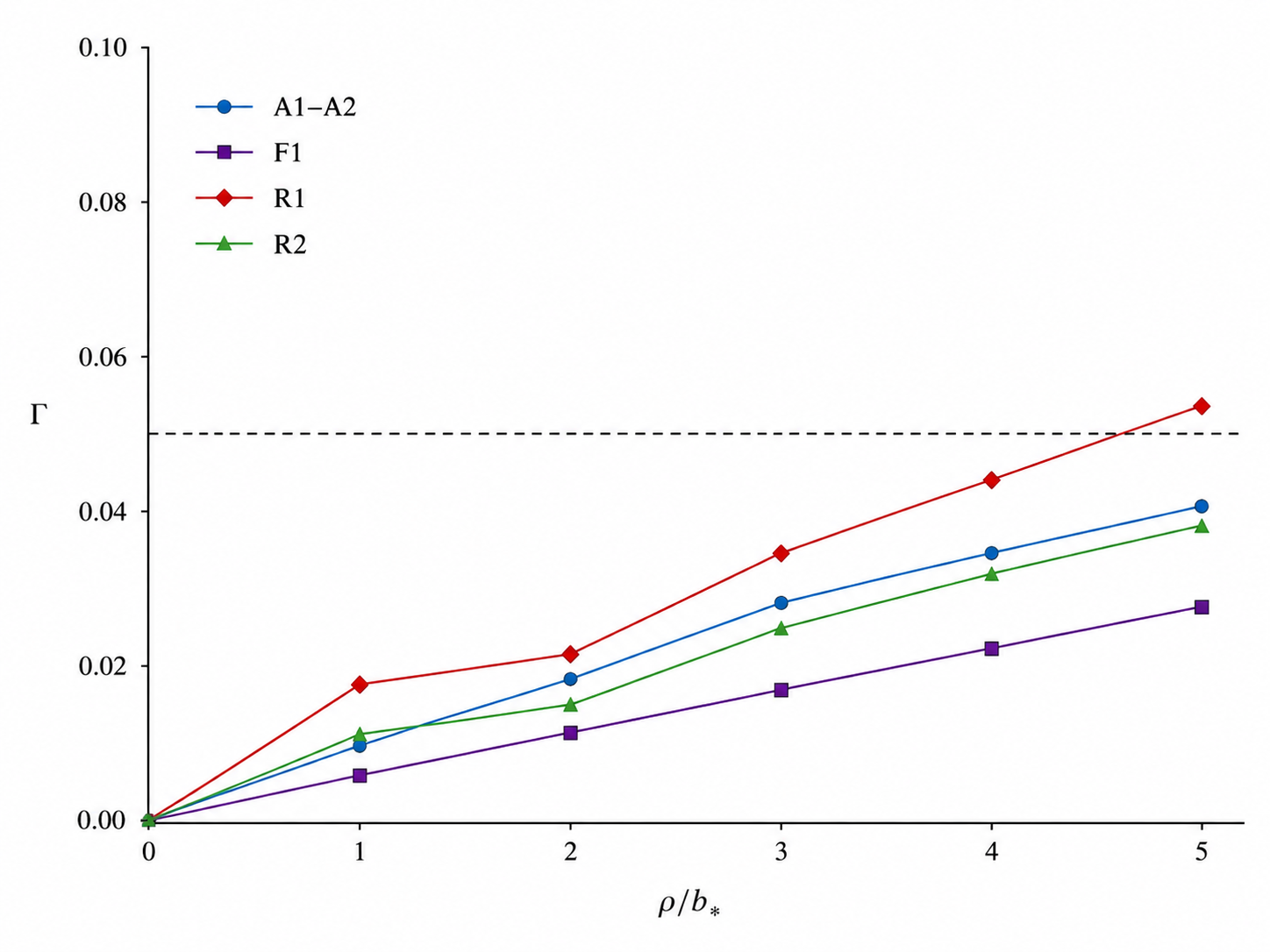
A graphical demonstration of the effect described by Eq. (25) is presented in Figure 10. One notices that a greater response change results from elongation of the outer edge compared to the inner edge. Translation of the interval also yields a higher change of the moment than simple extension of the edge. The latter observation may be relevant to fabricating catalytic coating, as deposition on an arbitrary finite interval becomes easier than coating exactly on the tip of a wedge.
The leverages from Table 6 constitute an easy-to-use endpoint placement guideline. Given that the outer derivative always exceeds the inner one, increasing the thickness of the layer away from the center or moving it further from the vertex represents the optimal strategy to improve the leading response. The suggested procedure should not be interpreted as a recommendation for relocating all coatings away from the vertex. Vertex proximity is appropriate when the flow is localized, while relocation is better for a larger first mode contribution.
Table 7 summarizes a number of design guidelines, which have been directly derived from the wedge test cases studied here. The calculation procedure makes a clear distinction between five adjustable parameters: wedge angle, sector radius, signed activity contrast, flux balance, and endpoint position. The wedge angle governs both the angular gain and the radial exponent. The sector radius influences the modal strength according to a power-law moment. Signed activity contrast determines the presence of cancellation of the first decaying mode. Flux balance controls long-range localization, and endpoint placement controls how efficiently a fixed catalytic length can be used.
The primary operational implication is that the length of the active region is not sufficient to ascertain whether the flow has any impact. It may be possible for an active sector that is close to the outside end of the patch to affect the flow more than a larger active sector near the tip end due to the amplifying nature of the wedge eigenmode on the radial moment of the far-field activity. If the objective is to affect a small-scale circulation near the corner, then the designer needs to design for patches that conserve flux and have a high value for the slip exponent.
| Design objective | Preferred configuration | Calculated basis |
| Maximize angular streamfunction amplitude | wider wedge with one dominant active wall | \(G_\Psi\) increases from 0.119 to 0.409 as \(\alpha\) rises from \(\pi/4\) to \(3\pi/4\). |
| Create compact vortices near a corner |
flux-balanced finite
patches in a narrow or right-angle wedge |
slip decays as \((b_*/\rho)^m\) with \(m\geq 3\) for \(\alpha\leq\pi/2\) in the evaluated cases. |
| Control far-field chemical signature | place finite sectors farther from the vertex | modal moments scale as \(b^\lambda_1+1-a^\lambda_1+1\), giving strong outer-sector weighting. |
|
Reduce interaction
between neighboring active corners |
enforce total flux balance and use smaller opening angles | removing the constant mode and increasing \(\lambda_1\) shortens the screening length. |
|
Cancel the leading
reflective-sector mode |
weaken the farther sector relative to the nearer sector | modal cancellation requires \(|A_f|/|A_n|=0.153\) for R1 and 0.086 for R2. |
| Increase response without adding coating length | translate a finite interval outward when device space allows | \(\mathcal{L}_\tau\) is larger for displaced and outer sectors than for vertex-attached sectors. |
|
Generate symmetric
pumping toward a bisector outflow |
activate both walls with compatible slip direction | two-wall actuation distributes the wall slip and produces a central counterflow. |
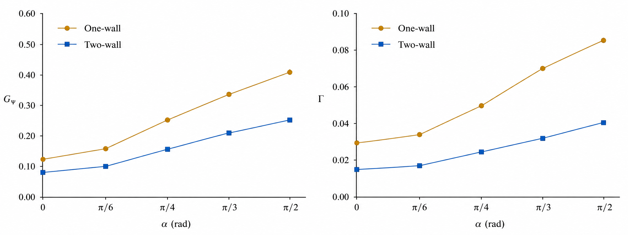
In Figure 11, the response sheet connects each design variable with a particular number value. Through the visual comparison, it is evident that stronger circulation, reduced screening, modal cancellation, and endpoint leverage rely on different geometrical characteristics rather than on the same activity scaling.
The analysis confirms that catalytic wedge-pore behavior depends on multiple parameters, not on just one strength characteristic. In the context of angle dependence, the identical total slip activity produces two distinct circulation distributions depending on the opening angle; with respect to the radial position, the physical length of coating has a varying effect on first-mode activity depending on its location; concerning the sign dependence, the opposing activities maintain a significant imbalance depending on the weighting of the far sector by the wedge eigenfunction. All these dependencies give us the answer to the design question posed in the title and explain the need for specifying the catalytic wedge-pore actuation with the full geometry: angle, radius, and sign are all equally important parameters.
The joint consideration of angle gain, signed balance, interaction and place sensitivity gives us a new way to interpret catalytic wedge-pore actuation. The logarithmic polar transform and modal moment representation constitute the main simplification: the solution to the two-dimensional harmonic-Stokes boundary-value problem reduces to a few exponents and moment weights dependent only on the angular and sector characteristics. These additional analyses allow us to answer three specific design questions not answered by modal moment representation alone. Namely, what is the extent of the interaction between sectors in terms of cancellation of the mode responsible for large response, what is the efficiency of slip transfer from near to far sectors, and finally, what is the angular lever of control exerted over the leading moment?
It is found that greater opening angle results in higher amplitude of the streamfunction under uniform slip forcing. Such increased angle, however, reduces the decay rate of the leading exponent. Thus, while providing larger circulation amplitude, wide angles come at the cost of decreased localization of the distribution. It means that wide angles are optimal for open corners with strong angular circulation, while narrow angles are advantageous when creating a more localized response in dense pores arrays. It is quite logical as discussed in the broader context of phoretic pumping, where geometry impacts both generation of slip and conversion to useful flow [32– 34, 37].
For a signed balance, reflectional symmetry does not lead to cancellation of first decaying modes since eigenfunction weight depends on distance: the further patch must be considerably weaker than the closer one in order to achieve effective suppression of first decaying modes. The wedge calculations reveal how strong such weakening should be: the residual percentage of leading signed moment after cancellation is as high as 73.4% for the \(4\pi/7\) reflecting wedge and increases to 84.2% for the narrower \(3\pi/7\) reflecting wedge. This sensitivity to separation implies that chemical similarity alone is misleading when two symmetrically paired sectors are radially apart.
The radial interaction index offers another perspective. The near sector cannot effectively affect flow near the far sector due to slip signature decay in the radial direction before the latter is reached. According to calculations, near-tip activity is quite efficient in terms of near-field dynamics (the value of index is low for both R1 = 0.049 and R2 = 0.026) but poorly effective in controlling the chemical gradient near the tip. Indeed, the further sector has a higher value of index due to first-mode integral weight being proportional to the radius power: \(\rho^{\lambda_1}\) favors larger radii. Such separation between effective vortex creation near the wedge corner and dominating modal response is crucial in terms of catalytic microfluidic geometries because coating close to the tip cannot serve as a perfect replacement to radial coating despite having equal coated length. Analogously to wedge geometry, diffusiophoretic dead-end pore transport may depend sensitively on the position of solute gradient imposition [11, 14, 15, 22].
The placement-sensitivity analysis provides a tool for optimizing sector shape. The positive derivative with respect to the outer edge and negative derivative with respect to the inner edge indicate that expansion of the sector in the radial direction is more advantageous than contracting. This trend is emphasized further by translation leverage of the sector. Displaced \((1,3)\) sector in the \(\pi/6\) absorbing wedge keeps 98.8% of first-mode strength of \((0,3)\) sector and has greater translation leverage, implying that moving an active sector away from the vertex allows creating the same modal effect with a shorter length. Such freedom in geometry optimization would be useful for catalytic devices because coating a finite-length interval would be preferable to coating a sharp tip.
The screening calculation becomes indispensable for estimating how localized modal response in a sector is and, hence, how feasible it is for device integration. For the right-angle finite-corner problem, predicted slip signature decay \((b_*/\rho)^3\) implies a rather short screening radius, only 2.71\(b_*\) (5%), so multiple active sectors in a channel are possible without significant interference. The screening results obtained for reflecting wedges are analogous, with screening radius depending on the wedge angle: the value of screening radius decreases from 2.97\(b_*\) (5%) for a reflecting wedge with opening angle \(4\pi/7\) to 2.46\(b_*\) (5%). For this reason, wedge angle regulates both the flow shape and the required separation among adjacent active zones.
Validity of the assumptions underlying the calculation defines its scope of application. The concentration field is assumed to be harmonic, a reasonable approximation when solute transport due to advection is much weaker than diffusion, that is, at low Peclet numbers. Such configurations have been shown to exhibit nontrivial phase transitions into nonlinear pumping regimes driven by reaction kinetics within the active regions [37, 38]. The hydrodynamics is formulated in the Stokes approximation, valid for micron-scale aqueous devices but inappropriate when inertia, buoyancy, and unsteady forcing become significant. Mobility in the interfacial layer is assumed independent of position along the boundary segments, whereas in real electrolyte systems it can depend on local concentration, pH, zeta potential, and the interaction length scale [21– 23]. These factors will impact the dimensional slip velocity, but they do not detract from the importance of geometric factors in shaping the flow pattern captured in the modal moments.
The matrix of angular gains, modal moments, signed balances, and interaction factors is to be used for initial geometric screening, but it is not intended to replace a full hydrodynamic flow simulation. Endpoint singularity effects, finite thickness of the interaction layer, rounding of vertex angles, and changes in mobility across the active region will modify the slip velocity near boundaries. Even the contribution of higher modes can affect the local slip near active region transitions. Nonetheless, the first-mode quantities provide useful information because they control the reach, relative weight, and cancellation within sectors. The latter are precisely those quantities that determine the catalytic patterns worth studying with a numerical Stokes flow calculation.
The same quantities can also serve as an objective criterion within the same model setup without altering the flow equations. Consider a vector \(\mathbf{a}\) denoting the sector activities. Suppose we wish to maximize clockwise circulation or minimize a weak chemical signature, and formulate the placement objective as \[\mathcal{J}(\mathbf{a}) = \left\|\mathbf{R}(\alpha)\mathbf{a}-\mathbf{q}_{\mathrm{target}}\right\|_2^2+\beta\|\mathbf{a}\|_1, \label{eq:objective} \tag{28}\] with the optimal response quantities stored in \(\mathbf{q}_{\mathrm{target}}\), and \(\beta\) being the penalty for catalytic material utilization. Since the elements of \(\mathbf{R}(\alpha)\) are explicitly given as functions of \(\alpha\), \(a_j\), and \(b_j\), one may evaluate the above expression prior to numerical hydrodynamics.
It is necessary to define uniquely the geometry of a wedge-pore system through its opening angle, endpoint coordinates, activity signs, boundary class, and choice of the mobility normalization. Lengths and activities alone are not sufficient for reproducibility since the radial placement alters the modal projections. Tabulation of quantities keeps the geometrical meaning intact: the wedge-pore configuration is stated first, angular gain follows next, the radius of screening is computed from the decay exponent, dominance and cancellation are separated, and each consequence is traced back to a numerical table entry.
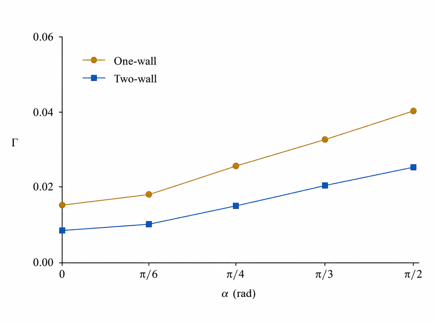
The fourth trend summary (Figure 12) also supports the choice of combined wall shape and opening angle: the one-wall case offers higher gain but less cancellation, while the two-wall case provides moderate gain and high cancellation.
The research questions addressed were whether geometric properties and catalytic layout of wedge pores suffice to determine circulation gain, radial localization, signed cancellation and sector positioning in the low Péclet number diffusio-osmotic and Stokes flow problem. The calculations have shown that they do suffice. Opening angle, radial position, and activity sign are all sufficient to determine several key design criteria: angular gain, screening radius, first-mode moment, signed residual, radial interaction, and endpoint leverage. These measures are not redundant: angular gain is used to estimate circulation amplitude, screening radius to determine radial reach, modal moment to measure sector dominance, signed residual to quantify cancellation error, and endpoint leverage to control sensitive placement.
The numerical solutions identify the main design options. Greater opening angles support larger circulations: increasing opening angle from \(\pi/4\) to \(3\pi/4\) raises the gain for the one-wall case from 0.119 to 0.409 and for the two-wall case from 0.076 to 0.249. Smaller or flux-balanced finite sectors support radial localization: the right-angle flux-balanced example features a screening exponent of three and a screening radius of \(2.71b_*\). Placement has a greater impact on modal distribution than mere activity length. The far sectors are much larger, by factors of 6.52 and 11.66, than the near sectors in the two reflective wedges, and the displaced \((1,3)\) sector maintains 98.8% of the first-mode intensity of the vertex-based \((0,3)\) sector.
Sign change highlights how the requirement of canceling circulation calls for modal rather than physical balance. Identical near and far opposite activities result in signed residues of 0.734 and 0.842, so that both the first-mode and the far-field response are unchanged. Complete cancellation of the leading mode can be achieved only by reducing the outer activity to 0.153 and 0.086 times the corresponding near-sector value. Radial interaction indices, \(0.049\) and \(0.026\), confirm the fact that while the near-sector forcing produces the dominant response locally, the contribution of the far-sector remains significant over large distances. Finally, the endpoint leverages add the final design rule: extending or translating outward produces a greater influence over circulation amplitude since modal weights increase monotonically with radius.
In short, the questions posed are answered by the derived numerical guidelines for designing catalytically-coated wedges. Wedge pores optimized for circulation generation would choose wide opening angles and large radial reach; wedge pores optimized for localization would employ narrow sectors or flux-balanced layouts and take advantage of faster screening of smaller or right-angle geometries; wedge pores designed to limit circulation leakage would balance signed modal contributions. Thus, these principles provide the means to select optimal coating layouts independently of material-specific reaction rates and finite vertex rounding.