
| AUSM | Advection Upstream Splitting Method |
| CFD | Computational Fluids Dynamics |
| C–J | Chapman-Jouguet |
| PDE | Pulse Detonation Engine |
| RDE | Rotating Detonation Engine |
| Roe–FDS | Roe Flux-Difference Splitting |
| UDF | User-Defined Function |
| ZND | Zel’dovich-von Neumann-Döring |
Aviation is responsible for up to 3% of annual CO\(_2\) emissions, highlighting the necessity of developing and implementing alternatives to traditional fuels, so this industry can reach the goal of zero emissions by 2050 [1]. The feasibility of the complete multidisciplinary system of a hydrogen powered aircraft has been proven with fuel cells [2] although gas turbines can still be utilized. Gas turbines offer flexibility in power generation and will remain crucial during the energy transition. Hydrogen’s impact on combustion, such as faster flame speeds and broader flammability limits, present safety and stability challenges. Combustion instabilities, flashbacks, and NO\(_x\) emissions are concerns, requiring advanced sensors and real-time monitoring [3]. Investigating alternative propulsion technologies contributes to the development of environmentally friendly solutions. The carbon emissions caused by the aviation industry are an urgent problem, with greenhouse gas emissions reduction, control of pollutants and efficient energy utilization current development trends. The performance of a rotating detonation engine (RDE) can be combined with energy-saving characteristics, under specific combustion chamber pressure ratios, which results in an increase of up to four times or greater. Also, the fuel consumption rate may decrease by 20%, for the same thrust levels, so the RDE demonstrates significant application potential, as it can reduce energy consumption, and improve engine performance [4].
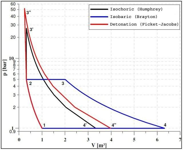
Combustion can be described as a chemical process where fuel and oxidizer are mixed, requiring ignition to initiate the reaction. The process generates a flame, controlled by heat conduction and radical diffusion. Combustion can be categorized into deflagration (low-pressure waves) or detonation (shock waves followed by combustion) with both increasing the temperature of the combustion products, but detonation generates higher pressure and temperature gains compared to deflagration [5]. Detonation follows the Fickett-Jacobs thermodynamic cycle, based on Chapman-Jouguet (C–J) theory and resembling the isochoric Humphrey cycle. Traditional turbo engines operate in isobaric open combustion, as that of Brayton cycle, where heat is added at constant pressure with necessary volume increases. Looking at Figure 1 it is obvious the pressure increase provided by heat addiction at isochoric conditions, with detonation representing the highest gain [6]. Combustion by detonation follows a thermodynamic cycle that, in theory, could increase performance up to 20%, compared to conventional deflagration combustors, either gas turbines and ramjets. Therefore, a combustor employing detonation represents a technological advance for more high-efficiency power systems, leading to higher thermal efficiency and better fuel consumption [7].
A detonation wave is a shock coupled with a chemical reaction that feeds such shock. Still in the 19th century, detonation was considered a plane wave without any particular internal structure, until unusual regimes were observed when propagating in tubes with circular cross sections [8]. Detonation wave have an intricate wave patterns formed within the detonation front, composed of cells resembling “fish-scales”, characterized by transverse shock interactions and regions of intense chemical reaction. These structures vary based on factors like gas composition and pressure, influencing the detonation’s propagation and reflection behaviors, particularly near surfaces [9]. Unlike sole shocks, the detonation wave compression is fed by the chemical reaction generated by the shock itself, in a self sustaining process. Besides, the detonation wave travels close to the C–J velocity. The C–J condition, which is applicable to detonations in high explosives, states that the detonation travels at a speed where the reacting gases reach sonic velocity relative to the leading shock wave as the chemical reaction completes. Initially proposed in 1900 for an infinitesimally thin detonation, the condition was later refined through the Zel’dovich-von Neumann-Döring (ZND) model in 1943, which offers a more detailed explanation of detonation behavior [10]. The ZND model is an idealized, one-dimensional depiction of gaseous detonations. It assumes there is a shock wave initiating the detonation, compressing and heating the gas, followed by a rapid chemical reaction in the reaction zone, transforming reactants into products. This reaction zone is relatively thin compared to the overall wave structure. The detonation wave propagates at a velocity where the gases reach sonic speed as the reaction ceases, aligning with the C–J condition. The model describes the transition from reactants to products, releasing energy to sustain the detonation, assuming a quasi-steady-state for simplified analysis [11].
Detonation engines were first theorized a long time ago, with the work of James A. Nicholls culminating in a predecessor of what today is known as a pulse detonation engine (PDE) [13, 14]. At the same time, B. V. Voitsekhovskii [15] observed the rotating characteristics of detonation waves in circular chambers. During the Cold War, American scientists eventually lost interest in detonation applications for thrust generation with some research being developed by the Soviet Union. Only in the present century, with natural gas power plants in vogue and conventional combustors near their maximum efficiencies, that the Americans regained interest in detonation engines, with proven feasibility experiments like those of Pratt & Whitney [16] where an operating envelop for injection pressure and oxygen enrichment of the hydrogen-air mixture was traced.
Pulse detonation engines (PDEs) have been the most tested propulsive equipment that uses detonation, consisting of a tube that’s cyclically filled with fuel and oxidant, followed by ignition and a detonation wave that travels across the mixture filled tube, with the product gases expanding to the exit, producing thrusts. The process is carried out 20 to 100 times per second, failing to provide a steady high level propulsive force [17]. Additionally, its long tube and need of a constant source of ignition make it difficult to integrate in gas turbines [18]. Even if the previous problems are overcome, only 45% of each cycle is effectively producing thrust, making it inefficient [19]. The RDE is the most promising combustion by detonation engine, due to it’s simplicity and high energetic density. For instances, the RDE only needs one ignition sequence, either by spark [20], wave generator (array of sparks) [21], gunpowder explosive charge [22] or tubular pre-detonator [23]. Further, there is no need for moving components, with the annular combustion chamber providing an optimal aerodynamic shape [24] and compact length that can be as short as the exhaust flow’s choking point [21]. Coupling the RDE with an aerospike has proven advantageous as so when integrated in a turboshaft engine, with power levels closes to those of traditional chambers, with the potential of an improved operating envelop [25]. The advantages of the RDE over the PDE include its ability to operate under wider conditions and Mach numbers, as well as providing a steady source of thrust without the need for frequent refueling, optimizing the time spent producing thrust. In the past, some authors defend the PDE shows better integration into airbreathing applications, while the RDE appears more suitable for the rocket engine [26] but contemporary studies have shown the amplitude of RDE applications. However, the RDE faces challenges such as achieving ignition with just a single detonation wave, handling injection in extreme pressure and temperature environments that limit component lifetimes, and managing potential backflow issues to the plenum [27]. The shock induced combustion ramjet (shcramjet) is a still low developed concept of an engine that also employs detonation for thrust generation in hypersonic air-breathing vehicles. This method of adding heat to supersonic flow provides additional compression, with less aggressive inlets and more rapid combustion compared to traditional ramjets and scramjets [28]. Nonetheless, the shcramjet has little applicability and only a few numerical studies are found, that find many engineering challenges such as combustion oscillations due to shock and boundary layer interaction, that travel upstream and can cause flame quenching [29].
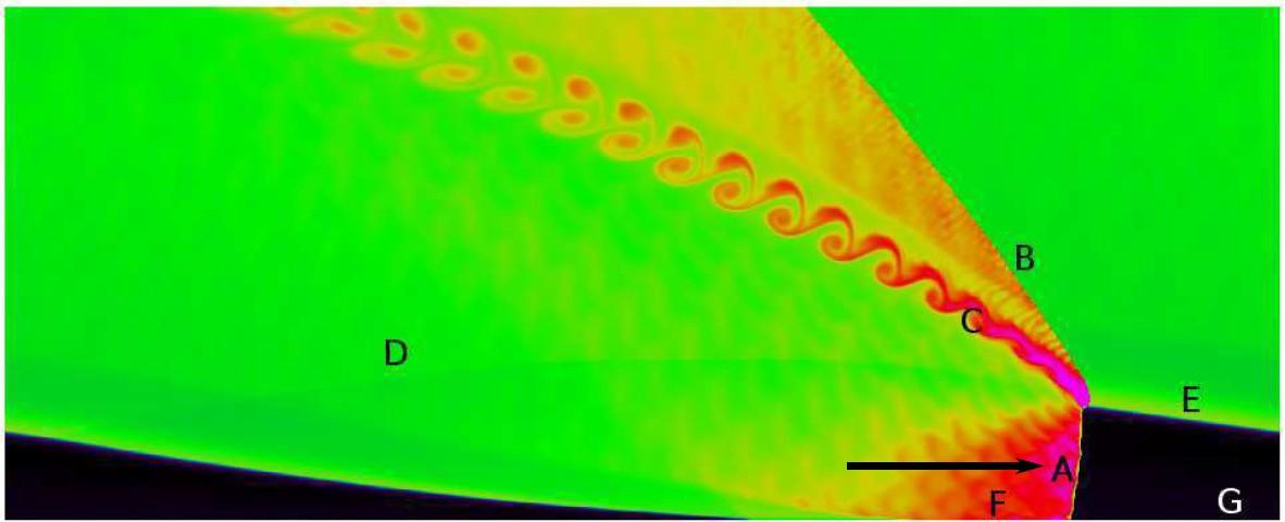
From ignition, the RDE is expected to have an unstable behavior, with contra-rotating detonation wave colliding and quenching, deflagration with hot spots that can degenerate into new detonation wave and co-rotating detonation wave catching up and strengthening. Eventually, one or more detonation wave should travel azimuthally around the chamber consuming the injected fresh mixture. Figure 2 shows an unwrapped numerical representation of an RDE in stable operation with one detonation wave A that is consuming the newly injected fresh mixture G. The high pressure combustion products in F block injection of new mixture and can even cause backflow and backpressure at the inlet. Eventually the products expand, accelerating in the axial direction. Hot combustion products interact in several structures, like oblique shock B that separates them from colder productions from previous revolutions of the detonation wave or slip line C that represents the passage from the detonation by the interface E between fresh mixture and products, a region with deflagration. D is a secondary shock wave, from the interaction of different temperature and pressure gas. The detonation waves often travels bellow C–J velocity due to curvature effects [30], with velocity, height and strength being strongly related and responsible for the stability within the chamber. Faster detonation waves need stronger detonation obtained from higher columns of fresh mixture, but the faster the detonation wave travels, the shorter will be the fresh mixture columns as there is less time for injection to recover and refuel the chamber. The more detonation waves there are simultaneously inside the chamber, the slower and weaker each individual detonation wave will be but higher frequencies and performance are achieved [30]. In fact, its expected that if the detonation waves are taller than half the combustor’s length, or some more elaborated relations between mass flow rate and chamber’s geometry, an instability that generates an additional detonation wave should be expected [31]. Factors, like injection, also play a significant role in the flowfield as more realistic injection models, opposing to the micro-nozzle ideal of Figure 2 will create elaborate interactions between fresh mixture and combustion products, as parts of the three-dimensional RDE base are walls.
Both numerical and experimental testing have been crucial for the developing of RDE by both proving its operability and understanding physical phenomena, allowing to define design parameters. Compared to experimental, numerical studies are low cost, highly effective and accessible, as many mature computational fluids dynamics (CFD) algorithms are available, representing indispensable tools for technological advances, and the RDE is no exception. Two-dimensional simulations are enough to capture most relevant flow field structures like detonation wave angle and height, the oblique shock and the interface shear layer and deflagration between products and fresh mixture. Three dimensional geometries will allow the exploration of further effects like curvature, mixing interactions and full detonation wave front structure. Overall, implications of design parameters like inlet and outlet pressure variations, injector geometry, walls, curvature, annulus thickness, chamber length, oxidant concentration, fuels and CFD parameters like combustion and turbulence models are just examples of the relevant information obtained with numerical studies, with the numerical model adapting to the investigation goal. Rankin [32], comparing experimental and numerical testing, found computational thrust is only 5% higher and detonation wave speed 8% lower. Phenomena like pressures oscillations inside the plenum, associated with the detonation wave, and affecting injection, were firstly and accessibly found through numerical studies [27]. CFD tools have been fundamental for novel findings in the past few years. Yan [33] studied the effects of plenum stagnation pressure, stagnation temperature, and heat release rate compared to inlet geometry and area ratio, underlying the relevance of considering the inhomogeneity and spacial discretization of realistic injectors. While investigating inlet backflow effects with quasi two-dimensional and three dimensional representations of the RDE, Paxson [34] found a novel instability, more prominent in chambers with higher levels of backflow, that increases the amplitude of area averaged manifold pressure in the inlet plane oscillations until collapsing and quenching detonation, resembling a compressor surge. Van Beck [35] studied NO\(_x\) formation, correlating it to detonation strength, with wave splitting proving an effective method to reduce emissions. It is even proposed the measuring of NO\(_x\) at the exit plane as an indicator of RDE stability. Li [36] suggested the consideration of wall film cooling in liquid kerosene RDEs, finding the extra oxidizer provided allowed a more efficient combustion of fuel vapors and faster recovery time of blocked injectors. Analytical studies are also important for fast integrating RDEs in conventional engines. Kaemming [37] evaluated the performance of a ramjet with an RDE for several flying Mach numbers, identifying sources of performance losses compared to ideal assumptions, like the blocking of the injection after the detonation wave passage, that causes flow imbalance between inlet and outlet. Nonetheless, the RDE ramjet is expected to outperform traditional ramjets for flight Mach numbers bellow 5.
Despite the steadily growing body of literature on RDEs, several challenges remain. The high computational cost associated with RDE simulations often necessitates simplifications and assumptions that may cause deviations between numerical results and real-world behavior. In the present study, a three-dimensional RDE is simulated using simplified CFD approaches with the objective of achieving realistic, reliable, and stable operation.
Two stoichiometric mixtures are investigated. Among them, only the hydrogen–air mixture allows stable RDE operation, whereas the hydrogen–oxygen mixture fails to achieve sustained detonation. This behavior may be attributed to limitations in grid and time-step resolution, as well as to the use of simplified numerical algorithms that struggle to accurately capture the extremely high temperatures involved.
For the case exhibiting stable operation, thrust and specific impulse are evaluated, together with pressure measurements at several monitoring points. In addition, the ignition phase and the unstable portion of the operation are analyzed in detail.
The novelty of this research lies in the highly descriptive presentation and thorough justification of the numerical model. A detailed description of the simulation setup and execution is provided, together with a clear identification of the limitations associated with the simplified numerical approach. By highlighting these aspects, this work contributes to guiding the scientific community toward achieving computationally affordable simulations of highly complex RDE systems.
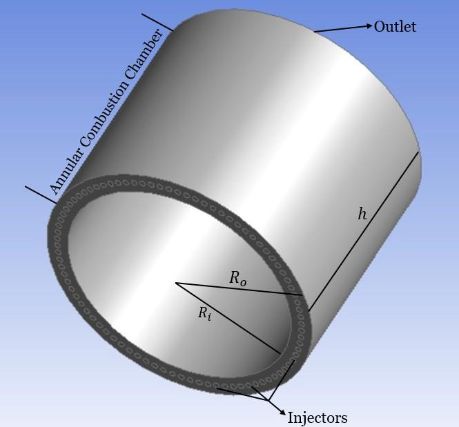
A small scale RDE was designed, as seen in Figure 3, with a length of 80 mm, inner diameter of 80 mm and outer diameter of 95 mm, corresponding to a chamber gap of 7.5 mm. 86 evenly spaced injectors, with a 2 mm diameter, are installed at the base head.
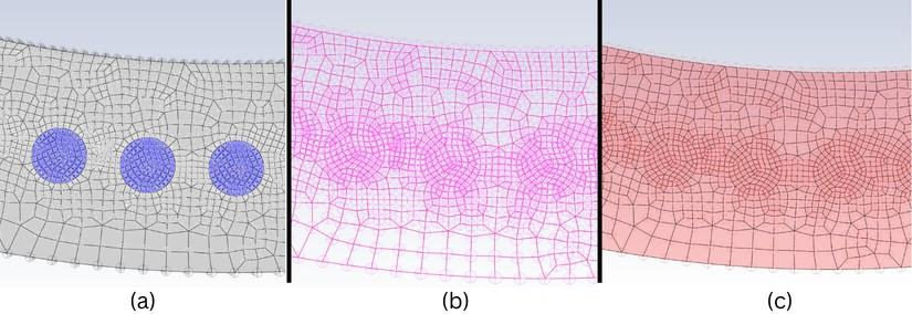
After assembling the geometry with CAD software, a three-dimensional grid is established. A hexahedral mesh is desired, although some parts of the geometry will have unstructured mesh as the only possible solution. A multizone mesh method was chosen, with injector’s face sizing and element size of 0.2 mm to improve overall quality. The detailing on the injector side of the mesh can be seen in Figure 4, with the total grid having 1929706 nodes and 1878633 elements. All elements have at least very good orthogonal quality and good skewness, with the majority being excellent, per Reference [38] standards. The model presented a maximum value of skewness of 0.8075 and an average of 0.21998. In terms of orthogonal quality, it presented a minimum of 0.45865 and an average of 0.9507. Therefore, the mesh is of good quality.
Ansys Fluent was the commercial tool chosen for solving the flow and coupling it with chemistry, with proven accuracy and fidelity for studies involving RDEs [39] and the software ability for parallel processing.
The pressure-based solver is highly versatile, capable of handling a wide range of flow regimes, from low-speed incompressible flows to high-speed compressible flows. It requires less memory and offers flexibility in the implementation of the solution procedure. The density-based coupled solver is best suited for flows where there is a strong interdependence between density, energy, momentum, and species. This makes it ideal for complex flow scenarios, such as high-speed compressible flows involving combustion, hypersonic flows, and flows with significant shock interactions. In the density-based solver, the equations for continuity, momentum, energy, and species are solved in vector form, while pressure is determined through an equation of state, and additional scalar equations are solved separately [38]. For this study, the density-based solver was chosen due to its effectiveness in handling high-speed compressible flows, particularly those with shock interactions. Although this solver tends to lengthen the simulation process, it provides the necessary trade-off to achieve convergence [40].
For gradient calculations, the Least-Squares Cell-Based method was used. To handle the flow, the Second Order Upwind scheme was selected for its advantages in managing complex flow conditions. For the turbulent kinetic energy and turbulent dissipation rate, a first-order scheme was applied to ensure stability and to reduce computational costs.
Regarding the flux type, Fluent offers two options: Roe Flux-Difference Splitting (Roe–FDS) and Advection Upstream Splitting Method (AUSM). Roe–FDS splits the fluxes based on their corresponding flux method eigenvalues, while AUSM is known for its accurate resolution of contact and shock discontinuities, and for being less prone to Carbuncle phenomena. Given these considerations, the AUSM flux type was chosen.
Turbulence was modeled with the realizable \(k-\epsilon\) as it has a wider applicability and faster convergence than \(k-\omega\) models [38], and its an evolution of traditional \(k-\epsilon\) models through the consideration of modern approaches to transport equations [41]. The SST K-\(\omega\) may represent a compromise as it applies the \(k-\omega\) model near the walls and the \(k-\epsilon\) model in the free stream, but still is more computationally expensive the realizable \(k-\epsilon\) with the advantages not relevant for this study. Besides, there are literature examples of the possibility of the utilization of \(k-\epsilon\) models for turbulence in RDE, like Li [36], Zhang [42] and Lu [43].
To handle the chemical process of combustion, species transport was selected as it suits a wide range of applications, including laminar, turbulent, premixed, non-premixed, and partially premixed systems. It balances accuracy and computational efficiency by modeling the mixing and transport of chemical species using conservation equations for convection, diffusion, and reaction sources. The volumetric reaction box was enabled, and the diffusion energy source option was selected to account for enthalpy transport in the energy equation. The model predicts the mass fraction of each species by solving the conservation equation for each chemical component. Reaction rates are computed using Laminar Finite-Rate, that assumes non-turbulent flow, calculating chemical reaction rates without turbulent mixing effects. The chemical models is obtained from the “Hydrogen-Air” 3 species- 1 equation mechanism within Fluent, with flow’s thermodynamic properties given by the ideal mixing-law. An ideal gas density is adopted.
Finally, for transient options, the second-order implicit formulation was selected due to its balance of accuracy and efficiency.
The wall boundaries have remained at default settings (stationary wall and no-slip condition). The boundary conditions for the inlet and the outlet are shown in Tables 1 and 2, respectively.
| Pressure Inlet | ||
| Momentum | Reference Frame | Absolute |
| Gauge Total Pressure | 1013250 Pa | |
| Supersonic/Initial Gauge Pressure | UDF – Pressure Inlet | |
| Direction Specification Method | Normal to Boundary | |
| Specification Method | Intensity and Viscosity Ratio | |
| Turbulent Intensity | 2% | |
| Turbulent Viscosity Ratio | 5% | |
| Thermal | Total Temperature | 300 K |
| Species Mass Fraction (hydrogen-air) | H\(_2\) | 0.029 |
| O\(_2\) | 0.230 | |
| Species Mass Fraction (hydrogen-oxygen) | H\(_2\) | 0.111 |
| O\(_2\) | 0.889 | |
| Pressure Outlet | ||
|---|---|---|
| Momentum | Backflow Reference Frame | Absolute |
| Gauge Pressure | 101325 Pa | |
| Backflow Direction Specification Method | Normal to Boundary | |
| Specification Method | Intensity and Viscosity Ratio | |
| Backflow Turbulent Intensity | 2% | |
| Backflow Turbulent Viscosity Ratio | 5% | |
| Thermal | Backflow Total Temperature | 300 K |
The goal of the present study is to have a sonic slotted injection, inspired in Duvall [44] layout, where choked injectors inject to the chamber stoichiometric already pre mixtured hydrogen and oxidizer. Accordingly to the descriptions of the flowfield, real injection should behave accordingly to chamber pressure, as follows:
\(P_{chamber}>P_0\) – Detonation has just occur and injectors are blocked, with no fresh mixture entering the chamber. Usually, injection recovers quickly but if this situation endures enough in time, backflow may occur. At this stage, injectors are susceptible to pass back-pressure into the plenum and reflect compression waves back into the chamber on the opposing direction of the detonation wave [45].
\(P_{cr}<P_{chamber}<P_0\) – Corresponds to an intermediary stage of injector recovery, where the combustion products are already expanding and traveling axially, having now pressure bellow that of the plenum, allowing for injection to reestablish. Pressure is still above critical values, so the inflow is subsonic, with velocity increasing with the chamber pressures decreases originated from further expansion of previous products.
\(P_{chamber}\leq P_{cr}\) – Chamber pressure as fallen bellow critical values, so the injectors are choked, reaching the maximum mass flow rate and with inflow velocities of sonic value.
\[P_{cr}=P_0\left(\frac{2}{\gamma+1}\right)^{\frac{\gamma}{\gamma-1}}, \tag{1}\]
So, for calculating the supersonic initial pressure, a User-Defined Function (UDF) was created. This function is also going to control the injection phase. It will analyze the current pressure inside the chamber and determine if the injectors will inject more mixture or not. It does this by reading the pressure inside the chamber and determining the supersonic initial pressure Fluent should assume.
\(P_{chamber}>P_0\) – There should be no flow (Mach = 0) and the supersonic initial pressure is equal to the stagnation pressure. This approach will allow the establishing of backflow if the chamber pressure is much greater than plenum total pressure.
\(P_{cr}<P_{chamber}<P_0\) – Injection is subsonic and the supersonic initial pressure equals the current chamber pressure.
\(P_{chamber}\leq P_{cr}\) – The supersonic initial pressure will be equal to the critic pressure and injection will be of sonic velocity (M=1).
As stated, this approach for modeling the RDE inlet won’t prevent numerical backflow which may cause some mass imbalances within the chamber, thrust losses and simplify the complex interface between fresh mixture and hot combustion products.
The goal of the simulation is to reach a level of maturity such that there is stable operation of one or more detonation wave. So the ignition of the numerical RDE must promote a shortening of the unstable initial operation in detriment of mimicking experimental ignition methods in order to save valuable computational resources. A similar approach to Zhang [46] allows the placement of a strip of fresh mixture near the injection face of an empty RDE, and, in a narrow section of such strip, place flow properties similar to those of the detonation wave.
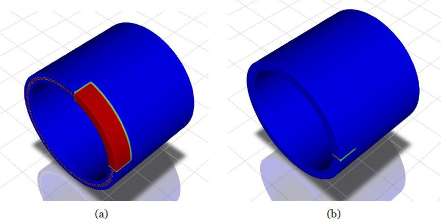
So, a hybrid initialization was utilized and then a standard initialization computed from outlet values, effectively creating empty RDE conditions. A first patch region of Figure 5 (a), at 20% of azimuthal distance and 20 mm axial height, was filled with fresh mixture at inlet stagnation pressure (1 MPa). The second patch region in Figure 5 (b) has the same axial distance and just 1 mm of azimuthal thickness. It is set to a pressure of 2.5 MPa, a temperature of 3000 K and azimuthally velocity of 1800 m/s.
Assessing of performance requires the measurement of exit conditions, namely velocity and pressure. For every time-step, values of mass flow rate, mass-averaged axial velocity and area-averaged pressure at the exit plane were registered. Further, three static pressure checking points are placed at the same azimuthal coordinate, at 0 mm, 40 mm and 80 mm (exit) from the injection base.
A time-set of \(1\times10^{-7}\) was adopted with a maximum of iterations of 75. If all residuals felt bellow \(1\times10^{-3}\), the domain would move to the next time-step.
The previously described numerical model was successful in igniting and produce a first detonation wave for both mixtures considered, with stable operation only achieved by the hydrogen-air mixture.
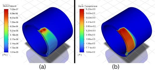
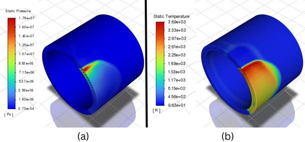
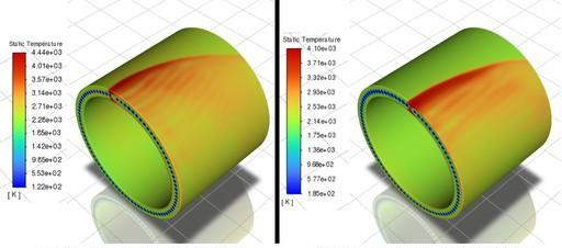
As the simulation is started from the prescribe initiation, an immediate detonation wave appears dominant in the anti-clock direction, as it travels trough the patched combustible mixture, and a secondary weaker detonation wave eventually begins to consume newly injected mixture in the opposing direction, as the shock from the initial patched pressure peak travels in both azimuthal directions and is strong enough to cause this secondary ignition. Figures 6 and 7 show the firsts stages of said detonation waves, being clear their propagation, and the beginning of a counter rotating secondarily detonation wave for each case, more imminent in the hydrogen-oxygen mixture.
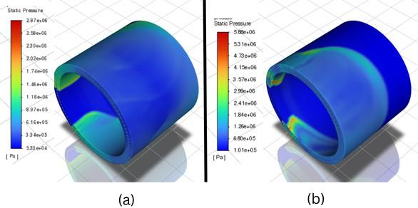
The detonation waves travel azimuthally consuming fresh mixture that is injected in the chamber, with the capturing of some non-idealities like deflagration of some combustible mixture in the products, observed by temperature increases without high pressure rises. Eventually, in each case, the two counter rotating waves collide, with Figure 8 showing the eminence of such event, where its evident that for the hydrogen-air case, the secondary wave is weaker.
Although there are some oddities in the hydrogen-oxygen RDE, maximum pressure and temperature are, respectively, 5.88 MPa and \(6.2\times10^{3}\) K compared to 2.87 MPa and \(3.7\times10^{3}\) K of the hydrogen-air. These values can be explained as the lack of dilution from nitrogen should make the detonation stronger and the lack of a more sophisticated model to account for dissociation of the products molecules.
Usually, a RDE after an initial unstable phase due to ignition or changing of some operating parameter like injection properties, reaches a state of stable behavior, characterized by a pseudo-steadiness, where one or more detonation wave travel azimuthally around the chamber at relatively constant speeds and heights.
For the RDE operating with the stoichiometric mixture of hydrogen and oxygen, deflagration happened and the detonation did not prevail after the two DWs collided, without signs of new detonation wave formation. Figure 9 (b) showcases such behavior where it is evident the fresh mixture throughout all of the RDE is immediately consumed. In Figure 9 (a) a shock is still observed but without any coupled chemistry, so it does not represent a detonation wave.
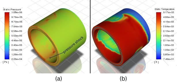
When pure oxygen is used instead of air, the energy release rate increases due to the higher oxygen concentration. This can lead to instabilities or pre-detonation reactions in the numerical model employed, which may prevent the formation of a stable detonation wave. Instead of transitioning to detonation, the mixture may sustain deflagration (a slower, subsonic flame front) due to these instabilities.
The initial conditions of pressure, temperature, and velocity also strongly influence the engine behaviour. Other numerical studies using stoichiometric hydrogen–oxygen mixtures have achieved stable operation [47], but they typically employ more sophisticated and computationally expensive algorithms.
On the RDE operated with hydrogen-air mixture, a single detonation wave dominated, traveling azimuthally around the chamber, as suggested by Figure 10. It can be observed that detonation wave strengthens after three revolutions around the chamber.
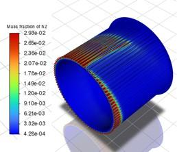
Figure 11 represents in an inner plane of the RDE chamber at half the gap the mass fractions of hydrogen. Fresh mixture can be seen in red near the injectors, with the blue region representing the combustion products from the current cycle while exhausting towards the exit. The detonation wavefront is moving in the anticlockwise direction and prepares to burn the fresh mixture ahead, whose columns extend to around two thirds of the RDE length. In fact, only the injector that has just experienced the passage of the detonation wave is blocked, while the previous injector, where the detonation wave has already passed, is already injecting fresh mixture.
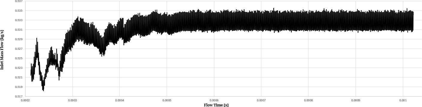
Based on the injection scheme chosen, the average inlet mass flow rate was approximately 0.531 kg/s and there was only one rotating detonation wave in the combustion chamber for the hydrogen-air RDE. During the entire computing process, data was recorded to allow the assement of the RDE performance. Some of the properties at the inlet and exit plane, specifically the inlet and outlet mass flow rate, outlet pressure, outlet velocity, engine thrust and mixture-based specific impulse are plotted to show the development of the properties and engine performance over the simulation time.
The inlet mass flow rate in Figure 12 increases as the gases of ignition leave the chamber and start the injectors, with the value having an oscillatory curve thorough stable operation, oscillating around the fixed value of 0.531 kg/s and an amplitude of less then 0.002 kg/s. As it was observed, the injectors have a very quick recover, meaning an injector may restart injecting fresh mixture just before the detonation wave reaches the subsequent injector.
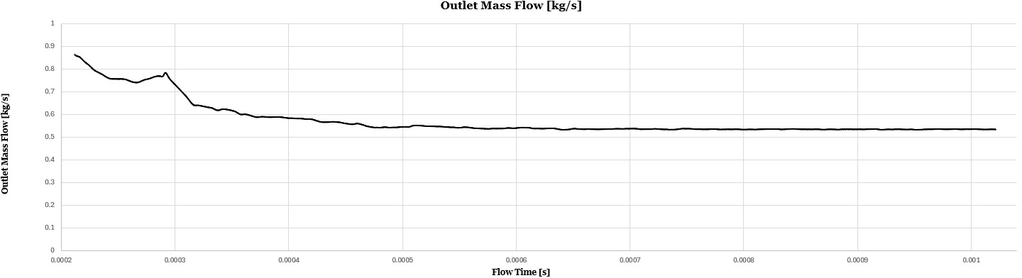
The outlet mass flow rate in Figure 13 has an opposite behavior. The exhaust of the ignition gases is evident as the mass flow rate decreases and reaches values close to those of inlet, proving the matching of inlet and outlet conditions.
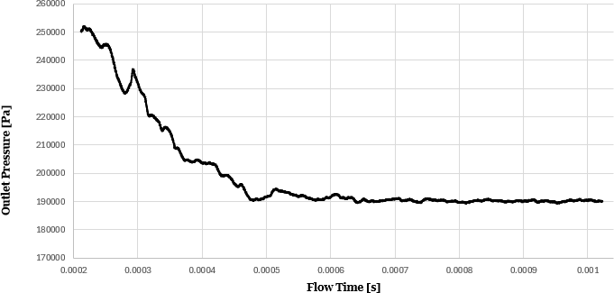
The outlet pressure curve in Figure 14 shows the exhaust of the numerical initialization highly pressure gases, decreasing its value until stabilizing around 190 kPa. The final value of outlet pressure, and the fact the exit is always supersonic, with an average Mach number of 1.12, it demonstrates the RDE chamber could beneficiate with the integration with a supersonic nozzle to further expand the flow and increase the specific impulse [48].
Outlet velocity of Figure 15 increases before stabilizing, confirming that during ignition more and more combustion products expand at the wake of the detonation wave.
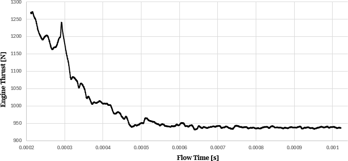
Due to the high pressured gases exiting the chamber during ignition, thrust in Figure 16 is higher during ignition than at stable operation. The specific impulse shown in Figure 17 exhibits a symmetric behaviour as the outlet mass flow rate decreases following the complete exhaust of the initiation products. Although thrust decreases, the component of specific impulse associated with momentum ejection is independent of mass flow rate and increases due to the higher exhaust velocity. Both thrust and specific impulse stabilize after a flow time of \(500\,\mu\)s, reaching values of 940 N and 179 s, respectively.
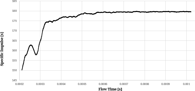
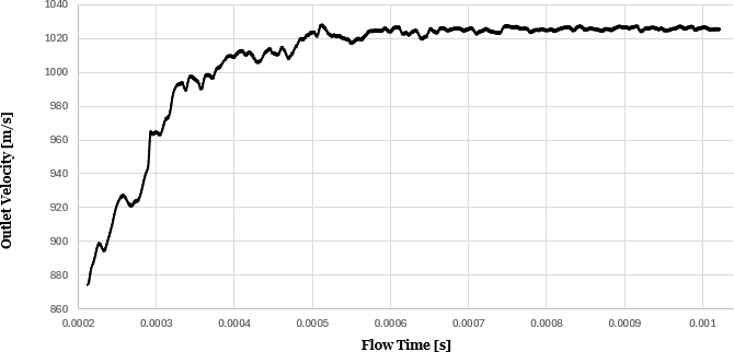
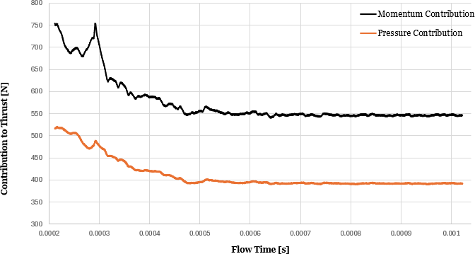
Figure 18 details the contributions for thrust of both momentum ejection and pressure differences. The momentum contribution to thrust is higher than the pressure contribution. The pressure term exhibits smaller variations and is therefore more stable than the momentum component. This indicates that the exit mass flow rate and exit velocity experience larger, and not necessarily coupled, variations compared to the outlet pressure. The fact that the momentum term represents the dominant contribution to thrust explains the behaviour observed in the specific impulse curve. Further, the three monitor points that were set at half the gap between two injector at the outlet, inlet and in the middle, recorded pressure values during the whole computing process to obtain the propagation information of the rotating detonation wave. When the detonation wave passes these points, their pressure recorded curves will present a peak, as shown in Figure 19. There are five peaks which means that the detonation wave passed five times through the monitor points.
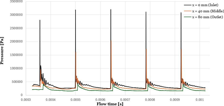
Regarding detonation wave velocities, it was calculated 1919.62 m/s for the first revolution, 1934.48 m/s for the second revolution, 1941.31 m/s for the third revolution and 1948.19 m/s for the fourth revolution. An accelerating trend is being observed for these intital instants of stable operation, proving the detonation wave is strengthening with each revolution.
Table 3 compares the obtained performance results at stable operation with those of similar studies found in literature, with the observable differences being explained by some implementation and operating choices.
| Studied Simulation | \(F=940\,\mathrm{N}\) | \(I_{sp}=179\,\mathrm{s}\) |
|---|---|---|
| Case 1 [49] | \(F=848.4\,\mathrm{N}\) | \(I_{sp}=173\,\mathrm{s}\) |
| Case 2 [49] | \(F=813.6\,\mathrm{N}\) | \(I_{sp}=165.9\,\mathrm{s}\) |
| Case 3 [50] | \(F=680\,\mathrm{N}\) | \(I_{sp}=200.4\,\mathrm{s}\) |
| Case 4 [51] | \(F=717\,\mathrm{N}\) | \(I_{sp}=169.4\,\mathrm{s}\) |
Cases 1 and 2 correspond to three-dimensional RDE simulations performed in ANSYS Fluent using stoichiometric hydrogen–air mixtures and a 7-species, 8-step chemical kinetic mechanism, with a mass flow rate of 0.5 kg/s. Case 1 employs a premixed injection scheme and yields a specific impulse very similar to the values reported in the literature. The small discrepancies observed can likely be attributed to differences in the injection configuration, while the slightly lower thrust may be associated with the marginally lower mass flow rate used in the present simulation.
In this case, only a single detonation wave was observed, propagating at a speed of 1963.4 m/s, which provides additional confidence in the reliability of the reported simulation results.
Case 2 represents a non-premixed RDE configuration, which results in lower thrust and specific impulse values. This outcome highlights the need for caution when interpreting premixed RDE simulations, as they may lead to an overprediction of engine performance.
Case 3 corresponds to an experimental RDE operating with an ethylene–oxygen mixture. The mass flow rate in this case is lower than that used in the present study, which results in a lower thrust. However, a higher specific impulse is observed, highlighting the advantages of using oxygen as the oxidizer, as a smaller total mass flow needs to be accelerated.
Lastly, case 4 corresponds to a 3D numerical study of a premixed stoichiometric hydrogen-air RDE with smaller geometric dimensions than the configuration considered in the present work. Consequently, the mass flow rate is also lower (0.439 kg/s), which results in reduced thrust. A lower specific impulse is also reported, likely associated with the injection configuration, which consists of arrays of holes that generate more chaotic detonation wave behavior. In this case, two detonation waves where observed which can be linked to the shorter azimuthal length of the RDE.
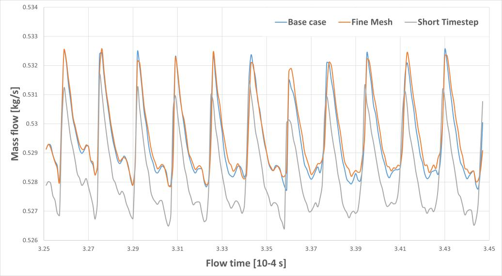
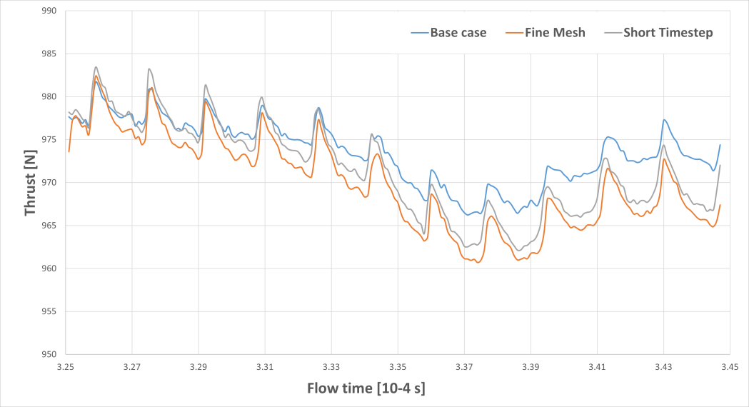
The original mesh consists of 1878633 cells and 1929706 nodes. To assess mesh sensitivity, a finer mesh with 2476251 cells and 2723406 nodes was generated. Additionally, the original timestep of \(1\times10^{-7}\) s was reduced to \(5\times10^{-8}\) s. Due to the significant computational cost associated with independence studies, the analysis was performed over timesteps 3250 to 3450 of the original case.
As shown in Figure 20, all cases exhibit similar inlet mass flow rate profiles, with oscillations associated with the dynamic blocking and reestablishment of injector holes. The refined mesh and reduced timestep predict slightly different mass flow rates; however, the differences are minor. The maximum deviation for the finer mesh is 0.436% at 0.0003590 s of simulated time. The shorter timestep generally yields slightly lower values, with a maximum deviation of \(-0.236\%\) at 0.0003342 s.
Regarding thrust, Figure 21 shows that similar trends are observed across all cases. The finer mesh tends to under-predict thrust for most timesteps, with a maximum deviation of \(-0.721\%\) at 0.0003441 s. The shorter timestep also frequently underpredicts thrust, although with a less consistent trend, reaching a maximum deviation of \(-0.578\%\) at 0.0003443 s.
Finally, differences in specific impulse are presented in Figure 22. The finer mesh again underpredicts the results, with a maximum deviation of \(-0.755\%\) at 0.0003440 s. The shorter timestep initially overpredicts and then underpredicts, with a maximum deviation of \(-0.417\%\) at 0.0003359 s.
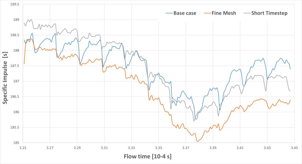
Overall, the increased computational effort does not lead to significant differences in the results or observed trends. Therefore, the original mesh and timestep are considered adequate for the purposes of this hydrogen-air study. However, a slight caution is advised, as performance metrics may be overpredicted by approximately 0.5%.
The presented results are the culmination of numerous simulations with many of them incomplete due to various challenges, ranging from cluster errors to Fluent software bugs or problems with convergence, as the respective numerical model had associated issues for the context of a RDE. The biggest challenge was to find an effective and appropriate combination of CFD options that addressed the required detail and specification of an RDE flowfield, at the lowest computational cost possible. Consequently, the final results represent the final steps of many months of rigorous simulations and iterative refinements, leading to the numerical models described.
In fact, the initial detonation wave in the oxygen-rich environment is slower, shorter, and exhibits a less defined front. This is particularly concerning, as the higher combustion temperature should increase the local speed of sound and therefore accelerate the detonation wave. Although higher temperatures and pressures than in the previous case were recorded, the slower detonation wave was an early indication that the simulation would likely fail to achieve stable operation.
A more refined grid or a smaller time step should be considered in future work to achieve a hydrogen–oxygen RDE under the prescribed dimensions and operating conditions, enabling the investigation of oxygen enrichment limits and behaviour. Additionally, a more sophisticated chemical model should be adopted, as the higher flame temperatures lead to significant dissociation effects that are more pronounced than in the hydrogen–air case. The present simulation produced temperatures exceeding 6000 K, which are not physically credible under the current modelling assumptions.
Even with a numerical ignition method that should only promote one initial detonation wave, two appear that will collide and delay the establishing of stable operation. It can impact real RDE behavior but it becomes an even more concerning mater in numerical domains when studies focus on stable operation flowfield. One possible solution could be launching a single detonation wave rotating, with the injectors starting in a sequence, pre following the detonation wave [52].
The expected C–J velocity of a detonation wave traveling through a stoichiometric hydrogen-air mixture is of 1968 m/s, expecting a static pressure increase from 15 to 20 times, which was observed. Flow properties for four full revolutions were registered with an average speed of 1935.9 m/s, and accelerating gaining confidence in the results, although this trend is not capture by flow’s properties. The detonation wave had a height of around two thirds of the chamber.
The simulation run for seven more revolutions registering only temperature colormaps to reduce computational cost and a pseudo-steady flowfield was observed, without signs of the instability reported by Paxson [34].
A limitation of this numerical RDE model lies in the over simplification of pre-mixed injection and the utilized UDF, that allowed backflow to establish due to high pressure of the detonation wave, above plenum stagnation pressure, but neglected the influence of its reinjection to the flowfield and performance. Effects from real injection schemes include detonation instability, catastrophic failure and plenum pressure oscillations. Nonetheless, the lost hot products at higher pressure are a very small fraction, as in stable operation there is an almost imperceptible mass unbalance.
All the oddities and unexpected behaviors observed in this study can be further studied, to understand how RDE numerical models can be further improved to mimic realistic operation with the ambitious goal of comprehending the fundamental mechanisms of RDEs and how to control them, so in-flight testing can come a step closer to reality.
A three-dimensional RDE was numerically simulated, capturing the different stages of operation, namely ignition, unstable behavior, and stable operation. A stoichiometric hydrogen–air mixture was employed, and careful consideration was given to the selection of CFD models and numerical schemes in order to balance physical fidelity and computational cost.
The simulation successfully reproduced the formation and propagation of a single detonation wave traveling azimuthally within the combustion chamber. During stable operation, this wave exhibited a strengthening behavior over successive revolutions, with its velocity approaching the theoretical Chapman–Jouguet (C–J) value. Despite this acceleration trend, no significant impact was observed on the global performance metrics, such as thrust and specific impulse, which remained relatively stable. The predicted performance values (approximately 940 N of thrust and 179 s of specific impulse) are consistent with results reported in the literature, supporting the validity of the numerical approach.
The model also captured key flowfield structures characteristic of RDE operation, including oblique shocks, slip lines, and the interaction between fresh mixture injection and combustion products. The injector dynamics, particularly the cyclic blocking and reestablishment of mass flow due to the passing detonation wave, were shown to play a critical role in shaping the oscillatory behavior of the inlet mass flow rate.
In contrast, simulations using a stoichiometric hydrogen–oxygen mixture failed to achieve sustained detonation. Following ignition, the system transitioned to deflagration, with only a decaying compression wave propagating through the chamber. This result highlights the strong sensitivity of RDE operation to both the fuel–oxidizer combination and the numerical modeling approach. In particular, the simplified chemical kinetics and numerical resolution employed in this study may not be sufficient to accurately capture the extreme thermochemical conditions associated with hydrogen–oxygen combustion.
Mesh and timestep independence studies demonstrated that the selected baseline configuration provides an adequate compromise between accuracy and computational cost, with deviations in key performance metrics remaining below approximately 1%. Nonetheless, a slight overprediction of performance on the order of 0.5% should be considered when interpreting the results.
Overall, this work reinforces the potential of RDEs as high-efficiency propulsion systems, capable of achieving improved thermodynamic performance compared to conventional deflagration-based engines, with possible reductions in fuel consumption of up to 20% as suggested in the literature [4]. At the same time, it highlights the significant computational and modeling challenges associated with accurately simulating such systems, including high computational cost, sensitivity to numerical parameters, and limitations of simplified physical models.
Future work should focus on the implementation of more detailed chemical kinetic mechanisms, improved turbulence–chemistry interaction models, and higher-resolution grids to better capture detonation physics. Additionally, further investigation into injector configurations, fuel–oxidizer ratios, and combustor geometries is necessary to enhance stability and performance. Finally, the environmental impact of RDEs should be assessed in greater detail, particularly with respect to emissions (e.g., NO\(_x\) formation) and noise, in order to support the development of cleaner and more sustainable propulsion technologies.
The authors are grateful for the financial support of the Fundação para a Ciência e a Tecnologia (FCT), I.P., through projects UIDB/0151/2025 and UIDP/0151/2025, Centre for Mechanical and Aerospace Sciences and Technologies (CMAST). DOI: https://doi.org/10.54499/UID/00151/2025. The authors are solely responsible for the content of this article, which does not reflect the opinion of the FCT.
This work was partially presented at the 59th Edition of the French Aeronautics and Aerospace Society International Conference on Applied Aerodynamics in Strasbourg, France on the 24th of March 2025. We thank the attendees for their valuable feedback.
The authors declare no conflict of interest.
Data will be available upon reasonable request.